A water distribution device with constant water head

A technology of water distribution device and fixed water head, which is applied in the direction of hydraulic model, etc., can solve the problems of large number of small flow pumps, cumbersome operation and management, arbitrary transfer, etc., and achieve the effect of convenient maintenance, saving water resources, light and compact

Active Publication Date: 2018-03-27
WUHAN UNIV
View PDF3 Cites 0 Cited by
  • Summary
  • Abstract
  • Description
  • Claims
  • Application Information

AI Technical Summary

Problems solved by technology

However, when the test requires a large flow range, the number of small flow pumps required will be large, which will cause certain financial pressure for scientific research personnel and cumbersome and inconvenient operation management.
At the same time, under the conditions of modern industrial assembly line production, the model of the water pump, that is, the interval change of the flow rate and the head is basically finalized, and the flow size requirements required by the testers sometimes cannot be solved by the combination of different flow rate pumps.
Even if it is a multi-stage adjustable water pump, its flow adjustment range is limited, and its flow adjustment interval is fixed, which cannot be adjusted arbitrarily according to the test requirements.

Method used


Image

  • A water distribution device with constant water head
  • A water distribution device with constant water head
  • A water distribution device with constant water head

Examples


Embodiment Construction

[0024] Below, the device of the present invention will be further described in conjunction with specific implementation examples and accompanying drawings.

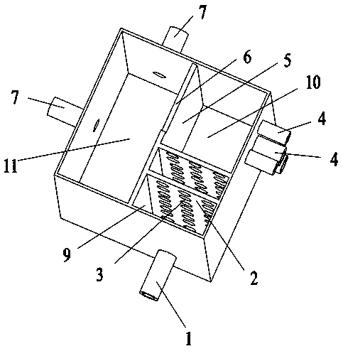
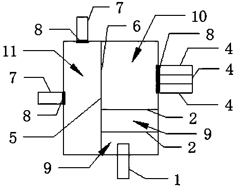
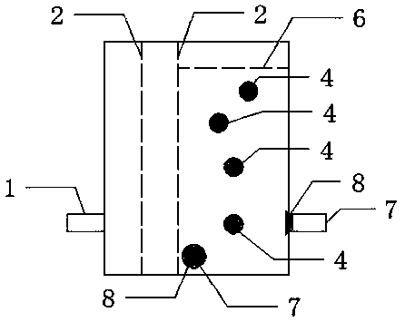
[0025] refer to Figure 1-Figure 5 As shown, a water distribution device with a constant water head includes a box body with an opening on the upper end surface, and the box body is provided with a partition plate 5 that divides it into two parts: the overflow chamber and the outflow chamber 11. The overflow chamber is provided with a baffle 2 that divides it into two parts of the turbulence chamber 9 and the static flow chamber 10. The baffle 5 and the baffle 2 are all vertically arranged, and the turbulence chamber The box body of 9 is provided with a water inlet pipe 1 connected to the water supply pipe, and the baffle plate 2 is provided with dense flow holes 3 to increase the inflow resistance to slow down the flow velocity of the water entering the box body and the impact it brings. Force, a groove is cut out on th...


PUM


Abstract

The invention discloses a flow-splitting water-distributing device of a constant head. The flow-splitting water-distributing device comprises a box with an opening in the upper end face, a flow-partitioning plate is arranged inside the box and used for dividing the box into an overflowing chamber and a flow outgoing chamber, flow-stopping plates are arranged inside the overflowing chamber and used for dividing the overflowing chamber into a turbulent flow chamber and a static flow chamber, a water inlet pipe is arranged on the part, in the turbulent flow chamber, of the box and connected with a water-supplying pipeline, densely-distributed flow passing holes are formed in the flow-stopping plates, and an overflowing groove is formed in the flow-partitioning plate between the static flow chamber and the flow outgoing chamber; multiple flow-distributing pipes of different heights are arranged on the part, in the static flow chamber, of the box, the highest flow-distributing pipe is lower than the overflowing groove, water outlet pipes used for discharging water are arranged at the part, in the flow outgoing chamber, of the box, and throttling devices are arranged on the water outlet pipes and the flow-distributing pipes respectively. According to a test flow design requirement, the excessive flow of incoming water can be regulated; redundant water is recovered through the water outlet pipes and prevented from being abandoned; the flow-splitting water-distributing device is simple in structure, convenient to apply and maintain and capable of being widely applied to a hydraulic power water flow test and hydraulic engineering needing flow-quantifying regulation.

Description

technical field [0001] The invention belongs to the technical equipment field of water conservancy facilities, and relates to a technical equipment for automatically and accurately diverting and distributing relatively large incoming water flow according to the requirements of the outlet water flow, in particular to a water diversion and distribution device with a constant water head. Background technique [0002] When carrying out water flow hydraulic tests in the field, it is often encountered that it is necessary to set different inflow flow levels to study test scenarios under different working conditions. Unlike laboratories with advanced scientific research equipment and good conditions for multi-stage adjustment of water supply equipment according to test flow requirements, field water flow hydraulic tests can only be supplied with constant flow and constant water head through single-stage water pumps. In order to meet the water flow requirements of different tests, a...

Claims


Application Information

Patent Timeline
Patent Type & Authority Patents(China)
IPC IPC(8): E02B1/02
CPCE02B1/02
Inventor 郭长强崔远来罗玉峰刘方平谢亨旺王少华
Owner WUHAN UNIV
Why Eureka
Try Eureka