
Plasma Bending Waveguide Filter Based on Microcavity Coupling Structure

A technology of bending waveguide and coupling structure, applied in waveguide-type devices, circuits, electrical components, etc., can solve problems such as poor performance and single function

Active Publication Date: 2018-10-19
GUILIN UNIV OF ELECTRONIC TECH
View PDF2 Cites 0 Cited by
  • Summary
  • Abstract
  • Description
  • Claims
  • Application Information

AI Technical Summary

Problems solved by technology

However, the existing plasmonic waveguide filters have problems such as single function or poor performance

Method used


Image

  • Plasma Bending Waveguide Filter Based on Microcavity Coupling Structure
  • Plasma Bending Waveguide Filter Based on Microcavity Coupling Structure
  • Plasma Bending Waveguide Filter Based on Microcavity Coupling Structure

Examples


Embodiment Construction

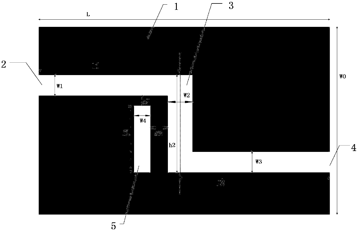
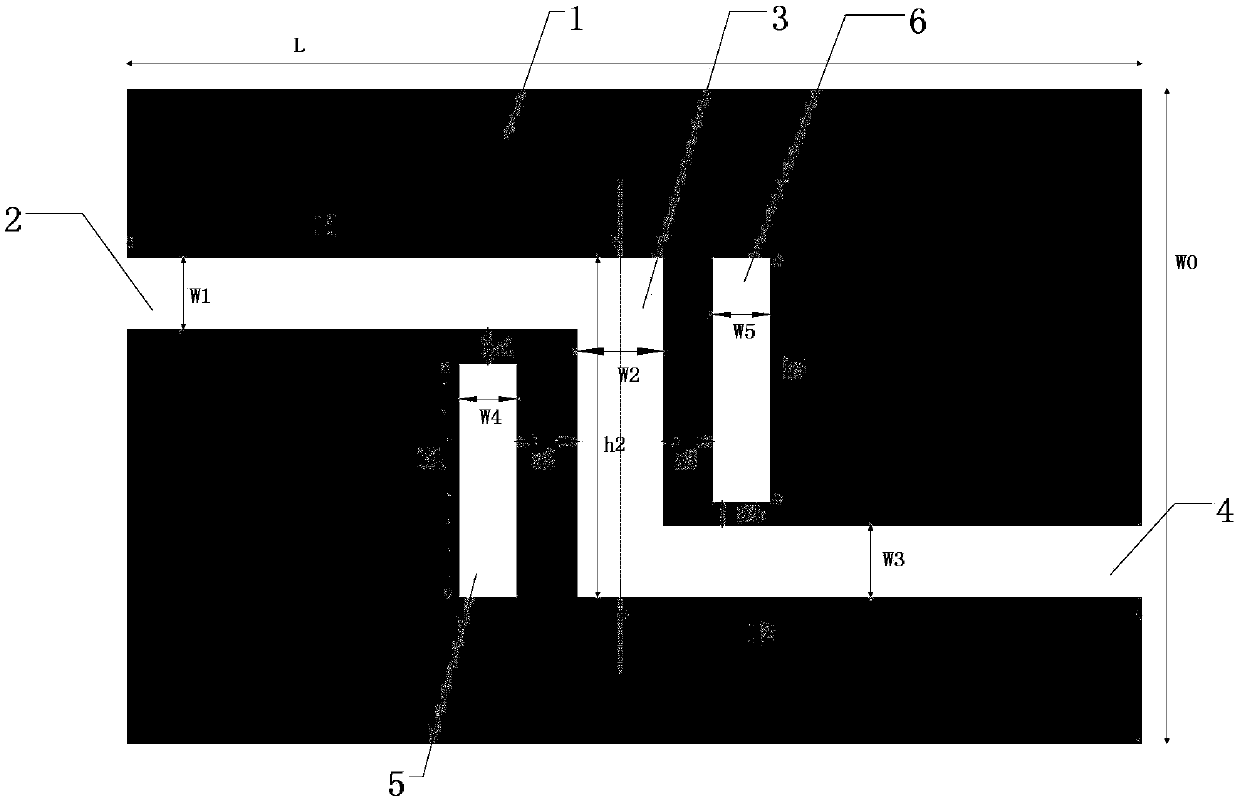
[0023] A plasma curved waveguide filter based on a microcavity coupling structure, comprising a metal thin film 1, a curved waveguide and a resonant cavity set on the metal thin film 1. In the present invention, the metal thin film 1 is a silver film, and the medium filled in the curved waveguide and the resonant cavity is air.

[0024] The curved waveguide consists of an incident waveguide 2 , an intermediate waveguide 3 and an exit waveguide 4 . The incident waveguide 2, intermediate waveguide 3 and exit waveguide 4 are all rectangular. The incident waveguide 2, the intermediate waveguide 3 and the exit waveguide 4 are sequentially connected end to end. One end of the intermediate waveguide 3 is connected to one end of the incident waveguide 2 to form a right angle connection. The other end of the intermediate waveguide 3 is connected with the outgoing waveguide 4 to form a right angle connection. The other end of the incident waveguide 2 extends to one edge of the metal ...


PUM


Abstract

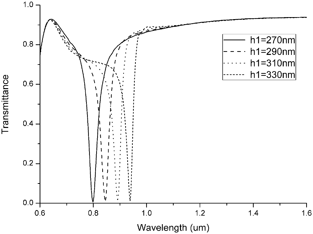
The invention discloses a plasma curved waveguide filter based on a microcavity coupling structure. The plasma curved waveguide filter comprises a metal film, and a curved waveguide and a resonant cavity which are formed on the metal film. The curved waveguide consists of an incident waveguide, a middle waveguide and an outgoing waveguide. The resonant cavity is disposed at one side and / or two sides of the middle waveguide. A straight waveguide is changed to a curved waveguide formed by two right angles, so that the middle waveguide can form an F-P cavity; moreover, two rectangular resonant cavities are added at two sides of the middle waveguide, a resonant coupling effect of the surface plasma polariton (SPP) is used to realize a filter function of the plasma polariton by adjusting the length of the resonant cavities; and in addition, the filtering and electromagnetic induction transparent effect can be realized by adjusting a distance between the resonant cavity and the waveguide, the length of the resonant cavity and the quantity of the resonant cavity, and a special coupling effect can be reflected.

Description

technical field [0001] The invention relates to the field of micro-nano photon technology, in particular to a plasma curved waveguide filter based on a microcavity coupling structure. Background technique [0002] In recent years, the ability of plasmonic waveguides to conduct light at sub-wavelength dimensions has attracted extensive attention from researchers at home and abroad, which has promoted the further development of plasmonic waveguide integrated passive devices. Among the various plasmonic waveguide structures that have been proposed, the metal-medium-metal (MIM) waveguide can support surface plasmon polaritons (SPPs) mode transmission and confine the modes in the dielectric layer, and has a strong local Domain capability, simplicity and ease of highly integrated advantages have great application potential in nano-integrated optics and devices. [0003] With the continuous development of science and technology, filters, as a carrier to remove noise interference, ...

Claims


Application Information

Patent Timeline
Patent Type & Authority Patents(China)
IPC IPC(8): H01P1/208
CPCH01P1/208
Inventor 肖功利刘利王宏庆刘小刚郑龙杨宏艳李海鸥李琦蒋行国
Owner GUILIN UNIV OF ELECTRONIC TECH
Learn More