
Gas charging device and gas charging method for gas chamber of GIS electric appliance

The technology of an inflatable device and an air chamber is applied in the direction of container filling method, container discharge method, container structure installation device, etc. It can solve the problems of high water content in the gas, the inability to effectively recover the gas, and hazards, and achieve simple operation , Convenient follow-up processing, convenient disassembly and assembly

Inactive Publication Date: 2017-01-04
STATE GRID PUTIAN ELECTRIC POWER SUPPLY +1
View PDF6 Cites 4 Cited by
  • Summary
  • Abstract
  • Description
  • Claims
  • Application Information

AI Technical Summary

Problems solved by technology

[0002] In recent years, with SF 6 GIS electrical equipment with gas as an insulating medium is widely used. Currently, GIS switches SF 6 The gas inflation method is to use SF 6 The gas cylinder is directly inflated to the GIS equipment, and each time the SF 6 When the gas is inflated, a certain amount of air will be brought in, and the air contains a certain amount of moisture, resulting in the SF in the air chamber of the GIS equipment 6 The gas contains too much water, and when there is too much water, it creates a hazard
[0003] SF in the atmosphere 6 is a cause of global warming, therefore direct emission of SF into the atmosphere is strictly prohibited 6 gas, while the remaining SF in the inflation pipeline in the existing inflation method 6 Gas cannot be recovered effectively

Method used


Image

  • Gas charging device and gas charging method for gas chamber of GIS electric appliance

Examples


Embodiment Construction

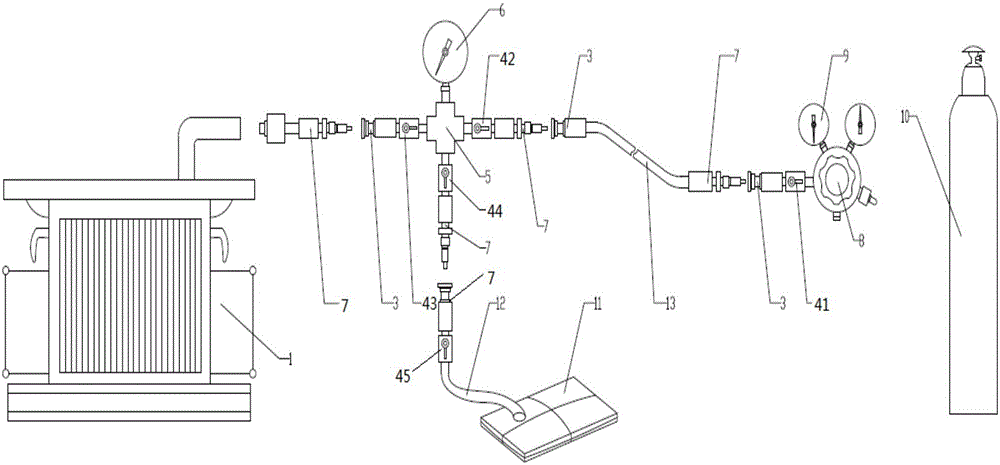
[0022] Examples, see figure 1 Shown, the gas filling device of a kind of GIS electrical appliance air chamber of the present invention comprises SF 6 Gas cylinder 10, decompression valve 8, inflation pipeline 13, also includes first gas recovery device 11, four-way joint 5, pressure gauge 6, first ball valve 41, second ball valve 42, third ball valve 43 and fourth ball valve 44 . The four-way joint 5 has four ports, which are sequentially defined as a first port, a second port, a third port and a fourth port. SF 6 The air outlet of the gas cylinder 10 is connected to the first port of the four-way joint 5 through the pressure reducing valve 8, the first ball valve 41, the inflation pipeline 13, and the second ball valve 42 in sequence, and the second port of the four-way joint 5 is connected through the third ball valve 43. GIS electrical appliance air chamber 1; the third port of the four-way joint 5 is connected to the first gas recovery device 11 through the fourth ball ...


PUM


Abstract

The invention discloses a gas charging device and a gas charging method for a gas chamber of a GIS electric appliance. The gas charging device comprises an SF6 gas cylinder, a pressure reducing valve, an gas charging pipeline, a first gas recovery device, a four-way joint, a pressure gage, a first ball valve, a second ball valve, a third ball valve and a fourth ball valve, wherein a gas outlet of the SF6 gas cylinder is connected with a first end hole of the four-way joint through the pressure reducing valve, the first ball valve, the gas charging pipeline and the second ball valve in sequence, and a second end hole of the four-way joint is connected with the gas chamber of the GIS electric appliance through the third ball valve; a third end hole of the four-way joint is connected with the first gas recovery device through the fourth ball valve; the pressure gage is installed on a fourth end hole of the four-way joint. The gas charging device also comprises a second gas recovery device and a gas cylinder filled with air. When gas is charged to the gas chamber of the GIS electric appliance, the SF6 gas bottle is replaced by the gas cylinder filled with air, and the first gas recovery device is replaced by the second gas recovery device. The gas charging device can be used for solving the problems that SF6 gas in the gas chamber of the GIS contains excessive water, and the residual SF6 gas cannot be recovered.

Description

technical field [0001] The invention relates to an inflating device, in particular to an inflating device and an inflating method for an air chamber of a GIS electrical appliance. Background technique [0002] In recent years, with SF 6 GIS electrical equipment with gas as an insulating medium is widely used. Currently, GIS switches SF 6 The gas inflation method is to use SF 6 The gas cylinder is directly inflated to the GIS equipment, and each time the SF 6 When the gas is inflated, a certain amount of air will be brought in, and the air contains a certain amount of moisture, resulting in the SF in the air chamber of the GIS equipment 6 The gas contains too much water, and when there is too much water, there is a hazard. [0003] SF in the atmosphere 6 is a cause of global warming, therefore direct emission of SF into the atmosphere is strictly prohibited 6 gas, while the remaining SF in the inflation pipeline in the existing inflation method 6 Gas cannot be effectiv...

Claims


Application Information

Patent Timeline
IPC IPC(8): F17C5/00F17C13/00F17C13/02F17C13/04
CPCF17C5/00F17C13/00F17C13/025F17C13/04F17C2205/0323F17C2205/037F17C2227/04
Inventor 庄建煌林挺周静黄伟
Owner STATE GRID PUTIAN ELECTRIC POWER SUPPLY
Learn More