
Liquid crystal display panel tray

A liquid crystal panel and tray technology, applied in the direction of preventing mechanical damage, packaging of vulnerable items, containers, etc., can solve problems such as glass corner damage, achieve the effect of ensuring shock absorption performance and avoiding local damage

Active Publication Date: 2016-12-14
WUHAN CHINA STAR OPTOELECTRONICS TECH CO LTD
View PDF8 Cites 6 Cited by
  • Summary
  • Abstract
  • Description
  • Claims
  • Application Information

AI Technical Summary

Problems solved by technology

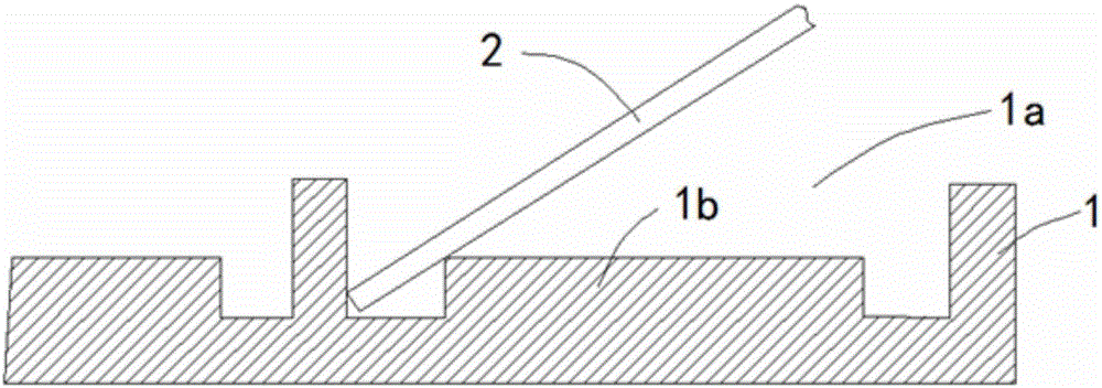
[0004] Although the tray of this structure achieves the purpose of liquid crystal glass shock absorption, its shock absorption structure brings new problems: when placing the glass 2, it is necessary to align the side of the glass 2 with the side of the slot 1a before placing it, so that One side of the glass 2 will be stuck in the gap between the second boss 1b at the bottom of the tray 1 and the side wall of the tray, resulting in damage to the corners of the glass

Method used


Image

  • Liquid crystal display panel tray
  • Liquid crystal display panel tray
  • Liquid crystal display panel tray

Examples


Embodiment Construction

[0023] In order to make the object, technical solution and advantages of the present invention more clear, the present invention will be further described in detail below in conjunction with the accompanying drawings and embodiments. It should be understood that the specific embodiments described here are only used to explain the present invention, not to limit the present invention.

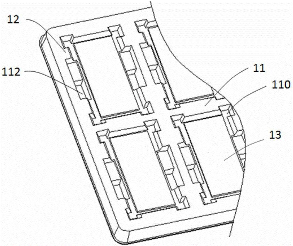
[0024] refer to figure 2 , the liquid crystal panel tray of the embodiment of the present invention comprises a main casing 11 and a plurality of grooves 110 arranged at intervals on the main casing 11, the bottom surface of the grooves 110 is higher than the bottom surface of the main casing 11; A first boss 12 is recessed in the groove 110, and a second boss 13 is formed in a recess from the bottom surface of the groove 110 toward the groove 110, and the boss surfaces of the first boss 12 are inclined towards the surroundings respectively (that is, toward the obliquely upward direction). til...


PUM


Abstract

The invention discloses a liquid crystal display panel tray. The liquid crystal display panel tray comprises a main shell body and a plurality of grooves formed in the main shell body at intervals. The bottom surfaces of the grooves are higher than the bottom surface of the main shell body. A first boss is formed by being inwards concaved from the lateral surface of each groove toward the inside of the groove. A second boss is formed by being inwards concaved from the bottom surface of each groove toward the inside of the groove. The boss surfaces of each first boss incline towards the four sides. The bosses are arranged at the bottom of the lateral wall of each groove of the liquid crystal display panel tray, and the boss surfaces on each lateral wall incline towards the four sides, so that a liquid crystal display panel is not prone to interfere with the lateral walls or the boss surfaces on the lateral walls, thereby not being clamped when taken and put, the phenomenon of partial damage to the liquid crystal display panel is avoided, and meanwhile the shock absorption performance of the tray is guaranteed.

Description

technical field [0001] The invention relates to the technical field of liquid crystal panel packaging, in particular to a liquid crystal panel tray. Background technique [0002] In order to protect the liquid crystal glass and facilitate storage or transportation, the liquid crystal glass is usually packaged in pallets. Small-sized mobile phone panels are usually packaged in blister trays, and each tray has multiple slots, such as figure 1 , the gap between each slot 1a of the tray 1 and the glass 2 needs to be designed to be very small, so as to play a buffer role in the horizontal direction and prevent the glass from being damaged due to violent shaking in the tray. [0003] At the same time, the bottom of the slot 1a of the tray 1 is generally designed with a second boss 1b to play a buffer role in the vertical direction, so as to prevent the tray 1 from being directly squeezed to the liquid crystal glass when the tray 1 is impacted by external force, and in order to in...

Claims


Application Information

Patent Timeline
Patent Type & Authority Applications(China)
IPC IPC(8): B65D1/34B65D81/02B65D85/48
CPCB65D1/34B65D81/02B65D85/48
Inventor 岳亮陈仕祥
Owner WUHAN CHINA STAR OPTOELECTRONICS TECH CO LTD
Learn More