Device for measuring distance from body connection sleeve V-shaped groove center to middle end face
A measuring device and body splicing technology, applied in the direction of mechanical gap measurement, etc., can solve the problems of poor product quality control, inability to meet mass production, low measurement efficiency, etc., and achieve the effects of cost saving, simple use and high measurement efficiency.
- Summary
- Abstract
- Description
- Claims
- Application Information
AI Technical Summary
Problems solved by technology
Method used
Image
Examples
specific Embodiment approach 1
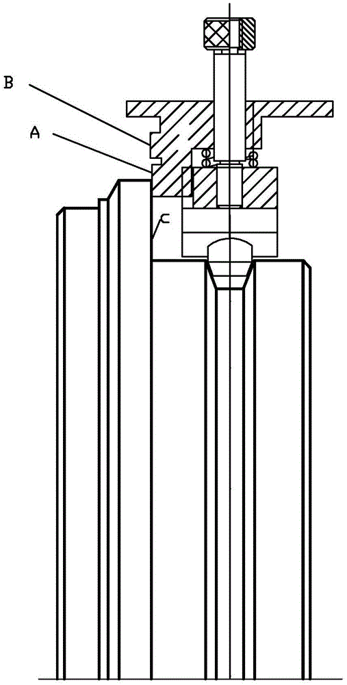
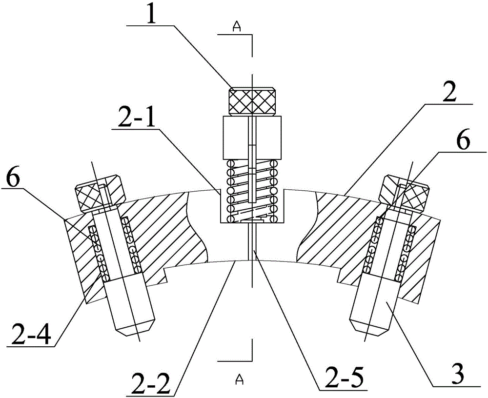
[0013] Specific implementation mode one: combine figure 1 , figure 2 , image 3 , Figure 4 and Figure 5 Describe this embodiment, a measuring device for the distance from the center of the V-shaped groove of the body joint to the middle end surface of the embodiment includes a bow-shaped plate 2, two positioning pins 3, a measuring plate 4, a first spring 5, and a fixed shaft 7 , two second springs 6 and three nuts 1,
[0014] The middle part of the outer arc of the bow-shaped plate 2 is provided with an outer arc groove 2-1, the upper part of the side wall of the bow-shaped plate 2 is provided with a through groove 2-3, and the middle part of the inner arc of the bow-shaped plate 2 is provided with an inner arc groove 2-2, and the outer arc The center of the groove 2-1 and the inner arc groove 2-2 is provided with a central hole 2-5, and the two sides of the inner arc groove 2-2 are respectively provided with a stepped hole 2-4, and the lower end of the fixed shaft 7 i...
specific Embodiment approach 2
[0022] Specific implementation mode two: combination Figure 5 and Figure 6 To describe this embodiment, the arc of the center line between the two stepped holes 2-4 of the inner arc groove 2-2 of this embodiment is 15°. In this way, the diameter of the stepped holes 2-4 is 337mm, so that the ratio of the chord length to the overall length of the measuring body is appropriate. Other compositions and connections are the same as in the first embodiment.
specific Embodiment approach 3
[0023] Specific implementation mode three: combination figure 1 Describe this embodiment, the fixed shaft 7 of this embodiment includes a reference cylinder 7-1, a threaded cylinder 7-2 and a lower end cylinder 7-3, a threaded cylinder 7-2, a reference cylinder 7-1 and a lower end cylinder 7 -3 are sequentially connected from top to bottom and made into one. Set up in this way, the threaded cylinder is to prevent the measuring plate 4 from slipping out by screwing the nut, the reference cylinder 7-1 cooperates with the inner hole of the measuring plate 4 to move the measuring plate up and down, and the lower end cylinder 7-3 is in contact with the center hole 2- of the bow-shaped plate. 5. The interference fit fixes the fixed shaft and the bow-shaped plate, and the step connection between the reference cylinder and the lower cylinder is convenient for assembly with a stop and a good limit. Other compositions and connections are the same as those in Embodiment 1 or Embodiment ...
PUM
| Property | Measurement | Unit |
|---|---|---|
| Diameter | aaaaa | aaaaa |
| Length | aaaaa | aaaaa |
| Diameter | aaaaa | aaaaa |
Abstract
Description
Claims
Application Information
 - R&D
- Intellectual Property
- Life Sciences
- Materials
- Tech Scout
- Unparalleled Data Quality
- Higher Quality Content
- 60% Fewer Hallucinations
Browse by: Latest US Patents, China's latest patents, Technical Efficacy Thesaurus, Application Domain, Technology Topic, Popular Technical Reports.
© 2025 PatSnap. All rights reserved.Legal|Privacy policy|Modern Slavery Act Transparency Statement|Sitemap|About US| Contact US: help@patsnap.com


