Substrate fixture

A fixed device and fixed position technology, applied in the direction of circuits, discharge tubes, electrical components, etc., can solve problems such as large-scale complex devices and substrate position deviation

Active Publication Date: 2019-06-04
NISSIN ION EQUIP CO LTD
View PDF4 Cites 0 Cited by
  • Summary
  • Abstract
  • Description
  • Claims
  • Application Information

AI Technical Summary

Problems solved by technology

[0004] However, in the substrate fixing device having the above configuration, since the substrate is fixed only by the two opposing sides, there is a possibility that the substrate may be shifted in a direction perpendicular to the opposing direction.
[0005] The above-mentioned problems are particularly noticeable when the ion beam implanter lifts up a horizontally placed substrate and injects the ion beam, and scans the substrate in a direction intersecting the ion beam.
[0006] On the other hand, if a jig is provided corresponding to each side of the substrate, actuators corresponding to the increased number of jigs are required, resulting in a complication of the device configuration and an increase in the overall size of the device.

Method used


Image

  • Substrate fixture
  • Substrate fixture
  • Substrate fixture

Examples


Embodiment Construction

[0073] An embodiment of the substrate fixing device of the present invention will be described below with reference to the accompanying drawings.

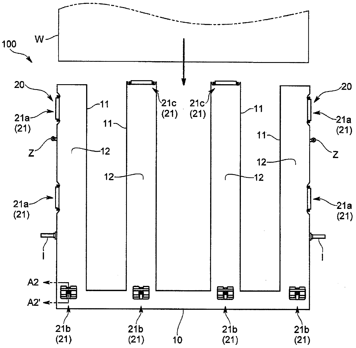
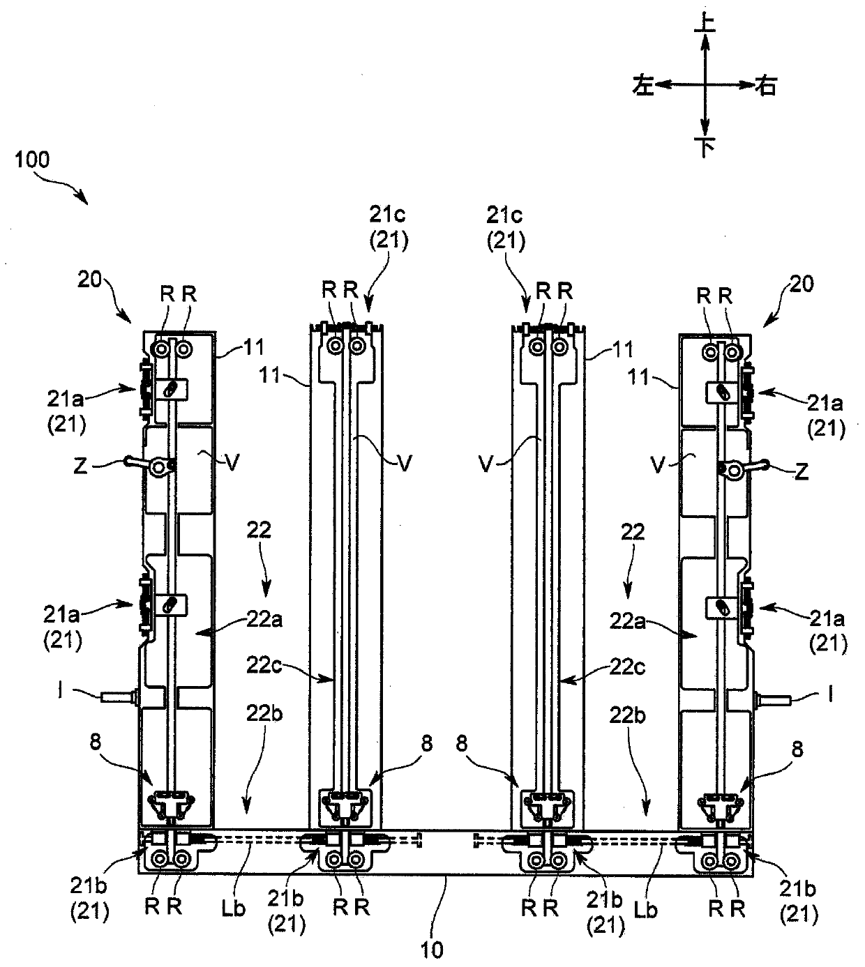
[0074] The substrate fixing device 100 of the present embodiment is, for example, used in an ion beam irradiation device and fixes a substrate W belonging to a processing object, and as figure 1 and figure 2 As shown, it includes a platform 10 on which a substantially rectangular thin-plate substrate W is placed, and a clamping mechanism 20 ; the clamping mechanism 20 fixes the substrate W between the clamping mechanism 20 and the platform 10 .

[0075] The above-mentioned platform 10 transfers the substrate W between a transfer robot (not shown), and is configured to be rotatable about an axis I between a horizontal posture on which the substrate W is placed and a standing posture raised from the horizontal posture.

[0076] In addition, the horizontal posture here includes postures leaning from the horizontal direction, and the...


PUM


Abstract

The present invention provides a substrate holding apparatus for surely maintaining a substrate (W) without complication of a structure of a device and enlargement of an entire device. The substrate holding apparatus comprises a platen (10) and a clamp device (22). The clamp device (20) comprises a plurality of clampers (21) and a power transfer device (22). The clampers (21) are included to correspond to each side of a substrate (W) and are able to move between a holding position (X) holding the substrate (W) and a releasing position (Y) releasing the substrate (W). The power transfer device (22) transfers a driving force for moving the clampers (21) between one side clamper (21) included to correspond to one of two sides of the substrate, which face each other, and the other side clamper (21) included to correspond to the other side of the substrate. The power transfer device (22) includes a slide member (7) sliding in a predetermined direction together with movement of the one side clamper (21) or movement of a member transferring driving force to the one side clamper (21) to transfer the driving force to the other side clamper (21).

Description

technical field [0001] The invention relates to a substrate fixing device for fixing a substrate. Background technique [0002] As for the above-mentioned type of substrate fixing device, there is a substrate fixing device as disclosed in Patent Document 1, which is an ion beam irradiation device for irradiating a substrate with an ion beam, and includes a stage and a chuck on which a substantially rectangular substrate is placed. A gripping mechanism; the gripping mechanism fixes the substrate between the gripping mechanism and the platform. [0003] Specifically, the clamping mechanism is provided with a pair of clamps and an actuator respectively provided corresponding to two sides of the substrate facing each other; the actuator is provided corresponding to each clamp so that each clamp is fixed at the fixed position of the substrate Move between the release position and the release substrate. [0004] However, in the substrate fixing device configured as described abo...

Claims


Application Information

Patent Timeline
Patent Type & Authority Patents(China)
IPC IPC(8): H01J37/317
Inventor 中泽喜之小野田正敏
Owner NISSIN ION EQUIP CO LTD
Why Eureka
Try Eureka