Proximity sensor calibration method and terminal
A technology of proximity sensor and calibration method, which is applied in the field of communication, and can solve problems such as large calibration errors, incorrect terminal placement, and calibration errors
- Summary
- Abstract
- Description
- Claims
- Application Information
AI Technical Summary
Problems solved by technology
Method used
Image
Examples
Embodiment 1
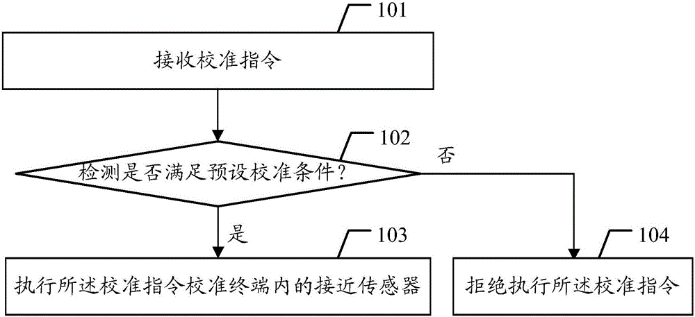
[0022] Such as figure 1 As shown, the calibration method of the proximity sensor of this embodiment includes the following steps:
[0023] Step 101, receiving a calibration instruction;
[0024] When the proximity sensor in the terminal needs to be calibrated, the operator can operate the terminal to send a calibration instruction, and the terminal receives the calibration instruction sent by the operator.
[0025] The function of the proximity sensor is to detect the distance between the object and the terminal. When the object is detected to be close to the terminal, the terminal is triggered to take corresponding protection actions to avoid misoperation. For example, for a terminal with a touch screen, when using the terminal to make a call, the proximity sensor is used to detect the distance between the face and the terminal, and when the distance between the detected face and the terminal is less than the preset distance, the screen lock action is executed , to prevent ...
Embodiment 2
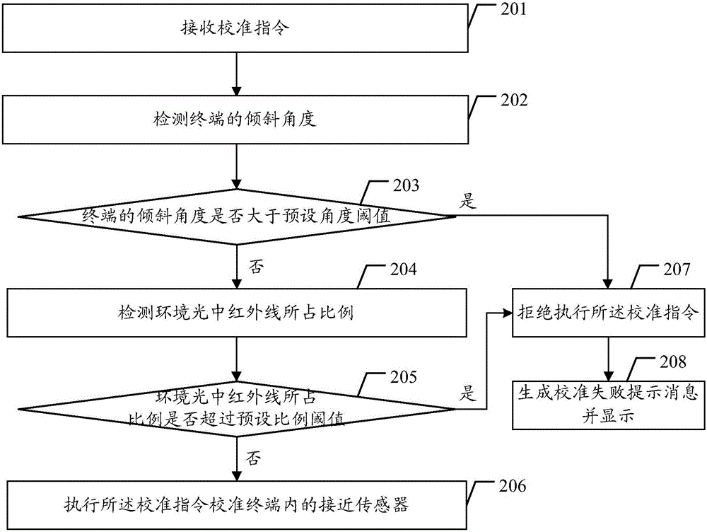
[0034] The method described in embodiment one, this embodiment will be described further, as figure 2 As shown, the method of the present embodiment includes the following steps:
[0035] Step 201, receiving a calibration instruction;
[0036] Step 202, detecting the tilt angle of the terminal;
[0037] In a specific implementation, a gravity sensor (G-sensor) may be used to detect the tilt angle of the terminal.
[0038] Step 203, judging whether the tilt angle of the terminal is greater than a preset angle threshold, if greater, then perform step 207, otherwise perform step 204;
[0039] The preset angle threshold can be set according to actual conditions, for example, 5 degrees, 10 degrees, etc., which are not specifically limited here. If the tilt angle of the terminal is greater than the preset angle threshold, it means that the base of the terminal is not in a horizontal position, and the tilt angle is too large. In this scenario, if the proximity sensor is calibrate...
Embodiment 3
[0052] In order to better implement the above method, the present invention also provides a terminal, such as image 3 As shown, the terminal of this embodiment includes:
[0053]a receiving unit 301, configured to receive a calibration instruction;
PUM
 Abstract
Description
Claims
Application Information
 - R&D Engineer
- R&D Manager
- IP Professional
- Industry Leading Data Capabilities
- Powerful AI technology
- Patent DNA Extraction
Browse by: Latest US Patents, China's latest patents, Technical Efficacy Thesaurus, Application Domain, Technology Topic, Popular Technical Reports.
© 2024 PatSnap. All rights reserved.Legal|Privacy policy|Modern Slavery Act Transparency Statement|Sitemap|About US| Contact US: help@patsnap.com


