Method for using guiding and locating box cone component and guiding and locating box cone

A technology of guide positioning and box cone, which is applied in the direction of mold boxes, casting molding equipment, metal processing equipment, etc., can solve the problems of increasing the weight of box cones, increasing the working intensity of box closing, and lack of meat in castings, so as to reduce labor intensity and reduce The difficulty of closing the box, avoiding the effect of rubbing sand

Inactive Publication Date: 2016-11-09
KOCEL EQUIP
View PDF6 Cites 3 Cited by
  • Summary
  • Abstract
  • Description
  • Claims
  • Application Information

AI Technical Summary

Problems solved by technology

However, this method still has many disadvantages: (1) The weight of the box cone is increased, and the working strength of the box is increased; (2) The size of the box cone is still relatively short compared with the upper and lower type, requiring multiple people to close the box at different angles at the same time, and the process is cumbersome (3) If the upper mold has many casting shapes, the box will be damaged due to collision, and the castings will have defects such as lack of meat and sand
The traditional box closing process generally only realizes the upper and lower mold matching by placing the box cone on the bottom mold. Since the stroke of the box cone does not change much, the box closing process is difficult, so the problem of wrong boxes on the upper and lower mold parting surfaces has not been improved.

Method used


Image

  • Method for using guiding and locating box cone component and guiding and locating box cone
  • Method for using guiding and locating box cone component and guiding and locating box cone
  • Method for using guiding and locating box cone component and guiding and locating box cone

Examples


Embodiment Construction

[0030] Embodiments of the present invention will be described in detail below in conjunction with the accompanying drawings.

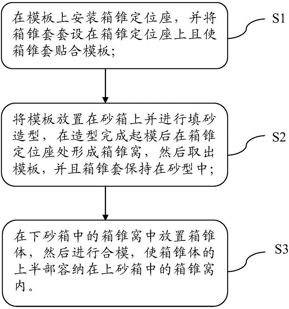
[0031] Such as Figure 1 to Figure 5 As shown, one embodiment of the present invention provides a method for using a guiding and positioning box cone assembly for casting production, including:

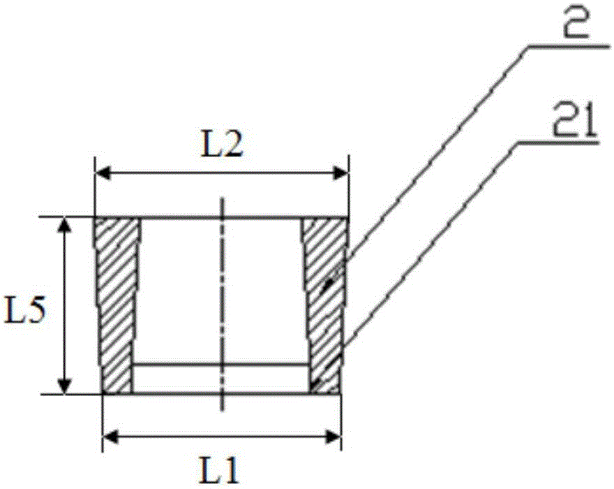
[0032] S1: Install the box cone positioning seat 3 on the template, set the box cone sleeve 2 on the box cone positioning seat 3 and make the box cone sleeve 2 fit the template;

[0033] S2. Place the template on the sand box and carry out sand-filling molding. After the molding is completed, the box cone socket 4 is formed at the box cone positioning seat 3, and then the template is taken out, and the box cone sleeve 2 is kept in the sand mold;

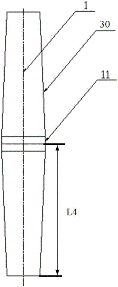
[0034] S3. Place the box cone 1 in the box cone socket 4 in the lower sand box 6, and then close the mold so that the upper half of the box cone 1 is accommodated in the box cone socket 4 in the upper sand box 5.

...


PUM


Abstract

In order to realize a purpose, the invention, on one hand, provides a method for using a guiding and locating box cone component used for casting production. The method comprises the following steps of mounting a box cone locating seat on a template, arranging a box cone sleeve on the box cone locating seat in a sleeving manner and further making the box cone sleeve abutted with the template; placing the template on a sand box, carrying out sand filling molding, forming a box cone nest at the box cone locating seat after the die stripping when the molding is completed, afterwards, taking out the template, and moreover, maintaining the box cone sleeve in a sand mold; and placing a box cone body in a box cone nest in a lower sand box, then carrying out die closing, and making the upper half part pf the box cone body accommodated in a box cone nest in an upper sand box. The invention also provides a guiding and locating box cone. By using the method for using the guiding and locating box cone component and the guiding and locating box cone, the box staggering can be prevented, and the sand rubbing in a box closing process can be avoided.

Description

technical field [0001] The invention relates to the technical field of casting, and more specifically, relates to a method for using a guiding and positioning box cone assembly for casting production and a guiding and positioning box cone. Background technique [0002] The most important link in the production process of castings is the boxing process, and the quality of boxing is directly related to the integrity of the produced castings at the parting surface. Therefore, care should be taken to prevent the upper and lower models from moving on the parting surface during the box closing process. However, castings produced by using the existing box cone are prone to misalignment at the parting surface. In recent years, some manufacturers have also introduced extended box cones, which lengthen both ends of the box cone to reduce the occurrence of wrong boxes during the boxing process. However, this method still has many disadvantages: (1) The weight of the box cone is incre...

Claims


Application Information

Patent Timeline
Patent Type & Authority Applications(China)
IPC IPC(8): B22C21/10
CPCB22C21/10
Inventor 徐海东
Owner KOCEL EQUIP
Why Eureka
Try Eureka