
Non-welding push-pull rod connecting structure of photovoltaic tracking support and solar tracker

A technology of solar tracker and connection structure, applied in the field of solar tracker, can solve the problems of not providing an ideal solution for push-pull rod connection, high cost, many processes, etc., and achieve the effect of easy on-site installation and adjustment, and simple production

Inactive Publication Date: 2016-10-12
SUZHOU JINSHAN SOLAR TECH
View PDF6 Cites 4 Cited by
  • Summary
  • Abstract
  • Description
  • Claims
  • Application Information

AI Technical Summary

Problems solved by technology

The advantage of this invention is that it has high adjustment accuracy, but it also brings problems such as complex structure, many on-site installation procedures, and high cost.
Therefore, none of the above solutions provides an ideal solution for the push-pull rod connection

Method used


Image

  • Non-welding push-pull rod connecting structure of photovoltaic tracking support and solar tracker
  • Non-welding push-pull rod connecting structure of photovoltaic tracking support and solar tracker
  • Non-welding push-pull rod connecting structure of photovoltaic tracking support and solar tracker

Examples


Embodiment 1

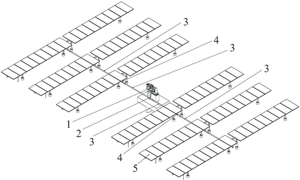
[0038] See Figure 5 and Image 6 , Solar automatic tracker can help solar photovoltaic or photothermal devices (such as photovoltaic panels, etc.) to better receive sunlight, to improve power generation efficiency, thereby reducing power generation costs. Among the existing automatic trackers, the linkage type parallel linkage mechanism has the advantages of simple structure, fewer driving components, and lower cost, and is widely used. The photovoltaic tracking bracket of the linked parallel link mechanism tracker is mainly composed of the driving device 1, the driving arm 2, the push-pull rod, the driven arm 4, and the component 5. The adjacent two rows of components are connected with the driven arm 4 through the push-pull rod to make The assembly 5 follows the rotation of the driving arm 2 to maximize solar energy and improve energy conversion efficiency.

[0039] The main function of the push-pull rod is to transmit the tracking angle of the driving arm 2 to the driven arm ...

Embodiment 2

[0049] Please refer to Picture 11 , Picture 12 , Figure 13 and Figure 14 The structure of the solderless push-pull rod connection structure of the photovoltaic tracking bracket of Example 2 is basically the same as the structure of the solderless push-pull rod connection structure of the photovoltaic tracking bracket of Example 1, and the functional effects are basically similar. The difference lies in: The first pull rod 30, the second push rod 31, and the adjustable rod 32 are all tubular. The push rod 30, the second push rod 31, and the adjustable rod 32 of the second embodiment are all rectangular.

[0050] Combining the two embodiments, it can be seen that the beneficial effects of the present invention are:

[0051] 1. The solar tracking array adopts the same push-pull rod structure, which is easy to realize standardized production in the factory;

[0052] 2. Both the push-pull rod and the adjustment rod are made of profiles, and the joints at the joints do not need to be ...


PUM


Abstract

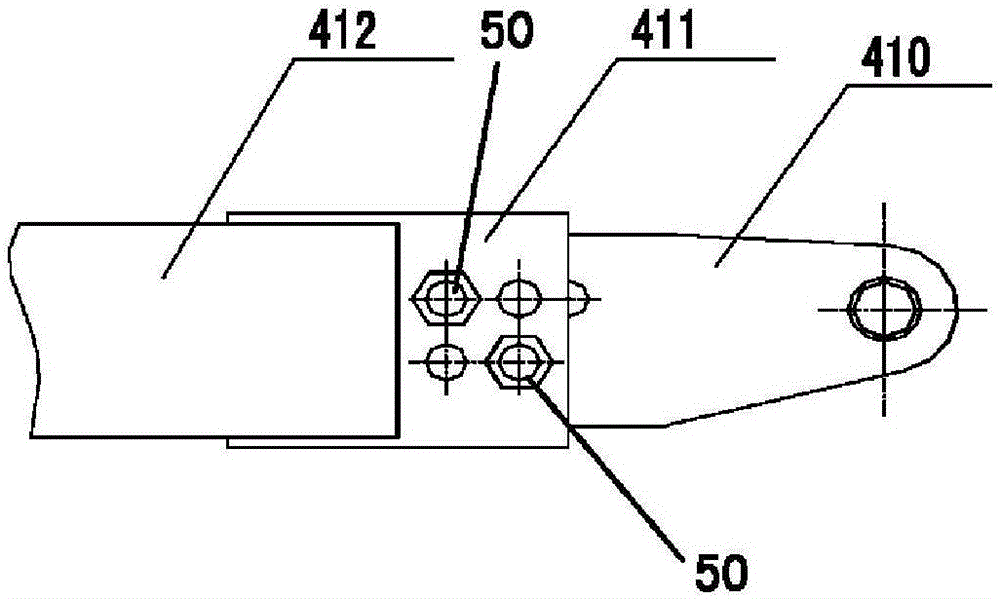
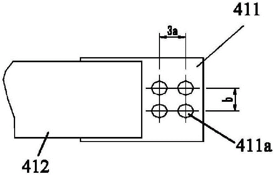
The invention discloses a non-welding push-pull rod connecting structure of a photovoltaic tracking support and a solar tracker. The push-pull rod connecting structure comprises a first push-pull rod, a second push-pull rod, an adjustable rod, a plurality of first connecting pieces, and a plurality of second connecting pieces corresponding to the first connecting pieces one to one. One end of the first push-pull rod is provided with a first plug-in port. Two opposite connecting base plates are arranged at one end of the adjustable rod, and an installation space is formed between the two connecting base plates. The other end of the adjustable rod is provided with a hollow second plug-in port. The first plug-in port is installed between the two connecting base plates and connected with the second connecting pieces through some first connecting pieces. The second push-pull rod is plugged in the second plug-in port and connected with the second connecting pieces through the other first connecting pieces. The push-pull rod connecting structure is easy to produce in a standardized mode in a factory; no welding is needed at joints, and manufacturing is easy; on-site installation and adjustment are easy.

Description

Technical field [0001] The invention relates to a push-pull rod connection structure, in particular to a welding-free push-pull rod connection structure of a photovoltaic tracking bracket and a solar tracker with the push-pull rod connection structure. Background technique [0002] The solar automatic tracker can help solar photovoltaic or photothermal devices (such as photovoltaic panels, etc.) to better receive sunlight to improve power generation efficiency, thereby reducing power generation costs. Such as figure 1 As shown, in the existing automatic tracker, the linkage type parallel linkage mechanism has the advantages of simple structure, fewer driving components, and lower cost, and is widely used. The linked parallel link mechanism tracker is mainly composed of the driving device 1, the driving arm 2, the push-pull rod 3, the driven arm 4, and the component 5. The adjacent two rows of components are connected with the driven arm through the push-pull rod, so that the comp...

Claims


Application Information

Patent Timeline
Patent Type & Authority Applications(China)
IPC IPC(8): H02S20/32F24J2/52F24J2/38F24S50/20
CPCF24S25/30F24S30/20F24S50/20H02S20/32Y02E10/47Y02E10/50
Inventor 文华强吴昊周印
Owner SUZHOU JINSHAN SOLAR TECH
Learn More