Touch control device

A touch device, touch display technology, applied in the direction of instrument, electrical digital data processing, input/output process of data processing, etc., can solve problems such as affecting detection results, and achieve the effect of accurate detection results

Active Publication Date: 2016-10-12
INTERFACE OPTOELECTRONICS SHENZHEN +1
View PDF9 Cites 5 Cited by
  • Summary
  • Abstract
  • Description
  • Claims
  • Application Information

AI Technical Summary

Problems solved by technology

However, this type of capacitive pressure sensor is easily affected by external factors, such as the deformation of the mechanism, the flatness of the electrode itself, and other factors that affect the detection results

Method used


Image

  • Touch control device
  • Touch control device
  • Touch control device

Examples


Embodiment Construction

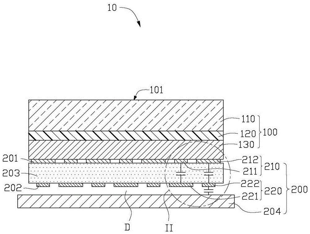
[0015] Please refer to figure 1 , figure 1 It is a schematic cross-sectional structure diagram of a touch device 10 according to an embodiment of the present invention. The touch device 10 of this embodiment can be an electronic product with a touch display function such as a smart phone, a tablet computer, or a game machine. The touch device 10 includes a touch display unit 100 , a signal sending layer 201 , a signal receiving layer 202 , an elastic body 203 and a metal frame 204 . The touch display unit 100 has a touch display surface 101 for displaying images and implementing touch operations. The signal sending layer 201 is formed on the side of the touch display unit 100 away from the touch display surface 101 , the signal receiving layer 202 is opposite to the signal sending layer 201 , and is farther away from the touch control layer than the signal sending layer 201 . Display unit 100. The elastic body 203 is located between the signal sending layer 201 and the sig...


PUM


Abstract

Provided is a touch control device. The touch control device comprises a touch control display unit having a touch control display unit. The touch control device comprises a signal sending layer, a signal receiving layer, an elastic body and a metal framework, all of which are arranged from the top to the bottom from the back side of a self touch-control display unit. The signal sending layer comprises multiple first signal sending units and multiple second signal sending units, all of which are arranged at intervals. The signal receiving layer comprises multiple first signal receiving units and multiple second signal receiving units. The first signal sending units and the first signal receiving units are arranged oppositely. The second signal sending units and the second signal receiving units are arranged oppositely. Air gaps exist between the metal framework and the signal receiving layer. The area of each first signal sending unit is less than that of each first signal receiving unit directly facing each first signal sending unit. The area of each second signal sending unit is less than that of each second signal receiving unit directly facing each second signal sending unit. The invention further provides a method for detecting touch pressing force by utilizing the above touch control device.

Description

technical field [0001] The invention relates to a touch device with a touch sensing function. Background technique [0002] In the existing touch display device, in order to detect the pressure of the touch to realize more touch functions, a pressure sensor is usually added to the touch display device, and the most common pressure sensor is a capacitive pressure sensor. The sensor includes opposite upper and lower electrodes. When a pressure touch occurs, the distance between the upper and lower electrodes changes, causing the capacitance between the upper and lower electrodes to change, and the touch pressure is converted according to the change in capacitance. However, this type of capacitive pressure sensor is easily affected by external factors, such as deformation of the mechanism, flatness of the electrode itself, and other factors to affect the detection result. Contents of the invention [0003] In view of the above, it is necessary to provide a touch device with ...

Claims


Application Information

Patent Timeline
Patent Type & Authority Applications(China)
IPC IPC(8): G06F3/044G06F3/041
CPCG06F3/0412G06F3/0414G06F3/044
Inventor 谢曜任王年杰
Owner INTERFACE OPTOELECTRONICS SHENZHEN
Why Eureka
Try Eureka