
Cup cover with cooling fan blowing and cup using the same

A technology for cup lids and fans, which is applied to drinking vessels and other directions, and can solve the problems of unclear working status marks, roughness and rigidity, etc.

Active Publication Date: 2017-07-07
平邑经发科技服务有限公司
View PDF4 Cites 0 Cited by
  • Summary
  • Abstract
  • Description
  • Claims
  • Application Information

AI Technical Summary

Problems solved by technology

In addition, the technical solutions disclosed in the above four patents all use the method of allowing the user to directly drive a power switch with a smaller volume than the cup lid to control whether the fan motor in the cup lid is working or not, and there is a working status indicator Inconspicuous defect, the present invention adopts the component that allows the user to drive the larger cup cover to switch whether the driving motor in the cup cover is working or not, so that it can be used conveniently and the working state of the cup cover can be improved. Obvious display so as to avoid possible misoperation; finally, in view of the existing disclosed technical solutions, adding parts such as fan drive motors on the basis of ordinary cup lids or adopting a split cup lid structure will easily cause rough and stiff appearance of the cup lid. The defect of stacking, the cup cover and the cup using the cup cover provided by the present invention also provide a technical solution for beautifying and decorating the shape by skillfully using additional parts or structures, so as to achieve the addition of functional parts and structures Compromise with appearance and beauty

Method used


Image

  • Cup cover with cooling fan blowing and cup using the same
  • Cup cover with cooling fan blowing and cup using the same
  • Cup cover with cooling fan blowing and cup using the same

Examples


Embodiment Construction

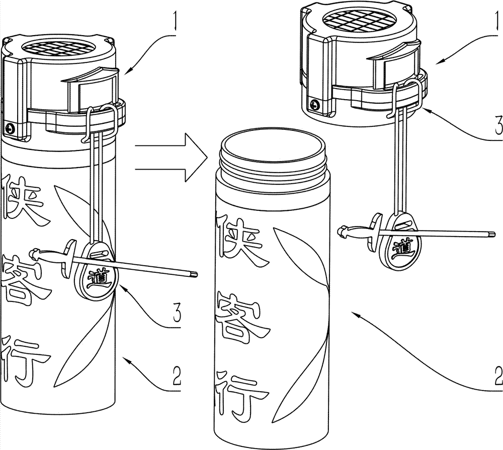
[0040] The present invention will be further described in detail below in conjunction with the accompanying drawings and two specific embodiments. Note that all the content in this section only provides several possible implementations of the present invention, and the implementation of the present invention is not limited thereto. .

[0041] attached in the manual figure 1 , image 3 and Figure 6 Shows the appearance of the two embodiments of the present invention, the way of blowing and heat dissipation, the method of use and the disassembly schematic diagram of the main parts. The rotating shaft 10 of rotating shaft 10 carries out horizontal rotation movement and conducts the power supply line of the motor 7 installed in the bowl cover. Such as Figure 6 As shown, the rotating shaft 10 is fastened to the edge of the connecting part of the cup cover and the mouth of the cup vertically upwards, and the part of the connecting part of the cup cover and the mouth of the cu...


PUM


Abstract

The invention provides a cup lid capable of cooling a liquid through a fan and a cup with the cup lid. A sealing lid, provided with a cup mouth sealing pad, of the cup lid can transversely rotate relative to the opening direction of a cup mouth; the fan capable of blowing air to a solution in the cup for cooling and a drive motor of the fan are arranged in a top cover above the sealing lid of the cup lid; the transverse movement motion, performed under drive of manpower, of the sealing lid enables a power supply circuit of the motor to be connected or disconnected through a motor power supply circuit connection device; when the sealing lid is rotated to be right above the cup mouth, the power supply circuit of the motor can be connected, and the fan can be driven to blow air to cool the solution; when the sealing lid is completely rotated away from the position right above the cup mouth, the power supply circuit of the motor is disconnected. The use method and the function of the cup lid are completely the same with those of a common cup lid except when the fan is used for blowing air to cool the solution, the fan is started for cooling and shut off by rotating the sealing lid integrated with the cup lid, and the cup lid has the advantages of convenience in use and attractiveness in appearance.

Description

technical field [0001] The present invention relates to a cup lid which is blown and cooled by a fan and a cup using the cup lid. The sealing cover on which the cup mouth sealing gasket is installed on the cup lid can perform lateral rotation movement relative to the opening direction of the cup mouth. The lateral rotation movement of the sealing cover driven by human power can connect the power supply circuit of the fan driving motor in the cup cover, and then make the motor drive fan blow the solution in the cup to promote cooling. Background technique [0002] Adding a fan driven by a rotating motor to the cup to blow the solution in the cup is a simple and direct product design idea to promote the cooling of the solution in the cup. At present, many technical solutions have been disclosed. For example, the application number is "CN201420658189.9 ", "CN200920001967.6", "CN200520104444.6" and "CN201120526839.0" are respectively named "a thermos cup with cooling device", "f...

Claims


Application Information

Patent Timeline
Patent Type & Authority Patents(China)
IPC IPC(8): A47G19/22
CPCA47G19/2288
Inventor 郭浣华陈榕杭张琳
Owner 平邑经发科技服务有限公司
Learn More