Multi-way valve

A multi-way valve and valve housing technology, applied in the field of multi-way valve, can solve the problems of increasing manufacturing cost, difficulty, controlling piston deformation, etc., and achieve the effect of reducing weight

Active Publication Date: 2019-07-05
FESTO AG & CO KG
View PDF9 Cites 0 Cited by
  • Summary
  • Abstract
  • Description
  • Claims
  • Application Information

AI Technical Summary

Problems solved by technology

However, this other known control piston presupposes that it is equipped with an annular sealing element on its outer circumference, which in turn increases the manufacturing costs.
The direct conversion of the control piston described in EP 2 092 226 B1 to a synthetic material piston becomes difficult in that the peripheral wall has regions of different wall thickness which shrink to different extents when the synthetic material hardens, which causes control Deformation of the piston

Method used


Image

  • Multi-way valve
  • Multi-way valve
  • Multi-way valve

Examples


Embodiment Construction

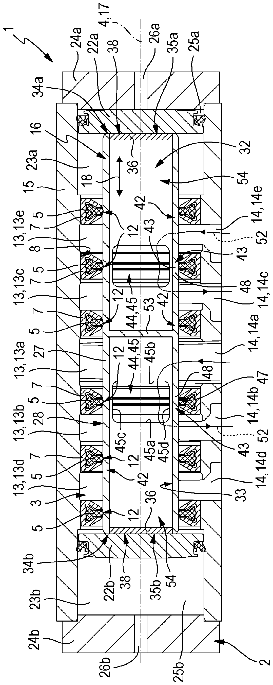
[0034] The multi-way valve 1 illustrated in the drawing in a preferred embodiment has a valve housing 2 in which an elongated housing recess 3 is formed and which has a longitudinal axis 4 .

[0035] A plurality of annular sealing elements 5 are arranged coaxially in the housing groove 3 and axially spaced apart from one another. The sealing element 5 is fixed in a stationary manner relative to the valve housing 2 in the axial direction of the longitudinal axis 4 . Preferably, each sealing element 5 is part of an annular sealing unit 6 which is fixed axially immovably coaxially with respect to the longitudinal axis 4 in the housing groove 3 . Each sealing unit 6 advantageously comprises an annular, U-shaped seal housing 7 in cross-section, the U-shaped hole of which points radially inwards in the direction of the longitudinal axis 4 and in which the respective annular sealing element is held. One of 5.

[0036] The sealing housing 7 is preferably pressed into the housing gro...


PUM


Abstract

The invention relates to a multi-port valve. The multi-port valve (1) comprises a control piston (16), wherein the control piston (16) comprises a peripheral wall (27) in a hollow column shape, and the peripheral wall can be divided into a plurality of locked segments (42) and overflow segments (43). Each overflow segment (43) comprises at least one overflow concave part (45) related to the adjacent segment (43) incurvating in radial direction. The overflow concave parts (45) form window-shaped wall cracks (44) of the peripheral wall (27) in a hollow column shape and are separately communicated by a piston cavity (32) surrounded by the peripheral wall (27). The colunmn-shaped external surface of the wall (28) of the peripheral wall (27) can extend on the locked segments (42) and the overflow segments (43). In corresponding switching position, fluid can pass through the overflow segments (43) and the piston cavity (32) and overflows between the axial adjacent groove segments (13) for holding a shell groove (3) of the control piston (16).

Description

technical field [0001] The invention relates to a multi-way valve with a valve housing (Ventilgehäuse), in which an elongated housing groove (Gehäuseausnehmung) is located, which housing groove is equipped with a plurality of mutually axially spaced and respectively radially inwardly directed annular sealing surfaces, wherein at least one of the annular sealing surfaces is arranged between two groove sections of the housing groove, in which at least one through Valve channel of a valve housing, in which a hollow control piston with a piston longitudinal axis is arranged in a housing groove, the control piston being displaceable axially along the longitudinal direction of the housing groove for positioning in different switching positions , and the control piston has a tubular peripheral wall surrounding the piston cavity radially outside with a peripheral wall outer surface, the peripheral wall has a plurality of locking segments arranged axially spaced apart from each other a...

Claims


Application Information

Patent Timeline
Patent Type & Authority Patents(China)
IPC IPC(8): F16K11/076F16K3/314
CPCF16K11/0716F16K11/0712
Inventor M.库格勒
Owner FESTO AG & CO KG
Why Eureka
Try Eureka