Tension control system for optical cable laying

A tension control and optical cable technology, applied in the direction of optical fiber/cable installation, etc., can solve the problems affecting laying efficiency and quality, uncontrollable optical cable tension, optical cable damage, etc. Effect

Inactive Publication Date: 2016-09-07
HENAN HONGJUN COMM ENG CO LTD
View PDF9 Cites 4 Cited by
  • Summary
  • Abstract
  • Description
  • Claims
  • Application Information

AI Technical Summary

Problems solved by technology

[0002] Optical fiber, referred to as optical fiber, is a light transmission tool that achieves the principle of total reflection of light in fibers made of glass or plastic. Optical cable is a cable core composed of a certain number of optical fibers in a certain way, with a sheath outside and a It is also coated with an outer sheath to realize a communication line for optical signal transmission. In the prior art, when the optical cable is laid, one end of the optical cable is fixed on the anchor pile, and the other end is directly connected to the tension machine. When the tension machine is in operation, the optical cable is pulled. Laying, the disadvantage of this technology is that it is impossible to control the pulling force of the optical cable. If the pulling force is too large, it will cause damage to the optical cable and affect the laying efficiency and quality.

Method used

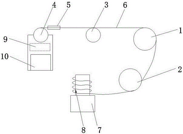
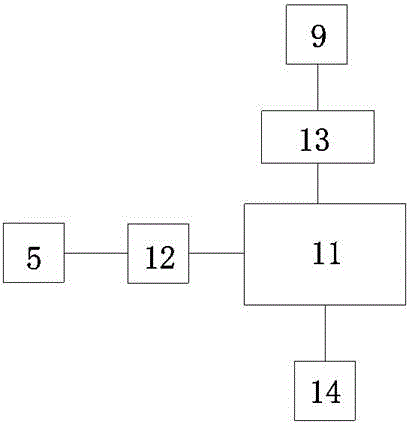
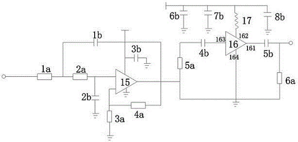

Image

  • Tension control system for optical cable laying
  • Tension control system for optical cable laying
  • Tension control system for optical cable laying

Examples


Embodiment Construction

[0014] The technical solutions in the embodiments of the present invention will be clearly and completely described below in conjunction with the accompanying drawings in the embodiments of the present invention. Obviously, the described embodiments are only some of the embodiments of the present invention, not all of them. Based on The embodiments of the present invention and all other embodiments obtained by persons of ordinary skill in the art without making creative efforts belong to the protection scope of the present invention.

[0015] see figure 1 , figure 2 , image 3 , the present invention provides a technical solution: a tension control system for optical cable laying, comprising a first traction wheel 1, a second traction wheel 2, a tensioning wheel 3, a tension machine 4 and a tension sensor 5, the first traction wheel 1 and The second traction pulley 2 is all fixed, and the second traction pulley 2 is arranged below the first traction pulley 1, and the tensio...


PUM


Abstract

The invention discloses a tension control system for optical cable laying. The tension control system includes a first traction wheel, a second traction wheel, a tensioning wheel, a tension machine and a tension sensor; the first traction wheel and the second traction wheel are fixed; the second traction wheel is arranged below the first traction wheel; the tensioning wheel is arranged at the front end of the first traction wheel; the center of the tension wheel and the center of the first traction wheel are on the same straight line; one end of an optical cable is fixed in a guide groove of a fixing pile; the other end of the optical cable is wound on the peripheries of the first traction wheel, the second traction wheel and the tensioning wheel and is connected with the tension machine; the tension sensor is fixed to one end of the optical cable which is adjacent to the tension machine; the tension machine is provided with a servo motor and a controller; and the controller is connected with the servo motor and the tension sensor. The tension control system of the invention is simple in principle. With the tension control system adopted, precise control on the tension of the optical cable can be realized, the tension can be prevented from becoming too large, so that the optical cable can be protected from being damaged, and the efficiency of optical cable laying can be improved.

Description

technical field [0001] The invention relates to the technical field of tension control, in particular to a tension control system for optical cable laying. Background technique [0002] Optical fiber, referred to as optical fiber, is a light transmission tool that achieves the principle of total reflection of light in fibers made of glass or plastic. Optical cable is a cable core composed of a certain number of optical fibers in a certain way, with a sheath outside and a It is also coated with an outer sheath to realize a communication line for optical signal transmission. In the prior art, when the optical cable is laid, one end of the optical cable is fixed on the anchor pile, and the other end is directly connected to the tension machine. When the tension machine is in operation, the optical cable is pulled. Laying, the disadvantage of this technology is that it is impossible to control the pulling force of the optical cable. If the pulling force is too large, it will cau...

Claims


Application Information

Patent Timeline
Patent Type & Authority Applications(China)
IPC IPC(8): G02B6/46
CPCG02B6/46
Inventor 袁丽红
Owner HENAN HONGJUN COMM ENG CO LTD
Why Eureka
Try Eureka