A magnetic force control circuit for electromagnetic poles of magnetic suspension bearings based on double bridge structure

A magnetic levitation bearing and magnetic force control technology, applied in high-efficiency power electronic conversion, control/regulation systems, electrical components, etc., can solve problems such as bus voltage short circuit faults, high real-time requirements, and complex control circuits, and reduce on-off losses , The effect of solving the hidden danger of instantaneous short circuit fault of the bus voltage

Inactive Publication Date: 2018-10-23
XIANGTAN UNIV
View PDF1 Cites 0 Cited by
  • Summary
  • Abstract
  • Description
  • Claims
  • Application Information

AI Technical Summary

Problems solved by technology

The speed of the magnetic levitation rotor is usually above 10,000 rpm, and the safety requirements are high. However, the working environment of the magnetic levitation bearing will inevitably have electromagnetic pollution. External interference makes the switch tubes Q1 and Q2 tubes conduct at the same time. Instantaneous short circuit fault in voltage
[0009] Magnetic levitation bearings generally have more than 20 inputs and more than 10 outputs, and have high real-time requirements. Currently, the products are implemented with multiple DSP systems, and the control circuits are complicated. For the high switching frequency, low power consumption and High reliability requirements, it is necessary to invent a control circuit for electromagnetic pole

Method used


Image

  • A magnetic force control circuit for electromagnetic poles of magnetic suspension bearings based on double bridge structure
  • A magnetic force control circuit for electromagnetic poles of magnetic suspension bearings based on double bridge structure
  • A magnetic force control circuit for electromagnetic poles of magnetic suspension bearings based on double bridge structure

Examples


Embodiment 1

[0101] Embodiment 1: as Image 6 , a magnetic suspension bearing electromagnetic pole magnetic force control circuit based on a double bridge structure, adopts a main circuit with a double bridge structure, and the main circuit includes 2 power switching devices and 2 diodes: a first power switching device (Q1), a second power switching device (Q1), Two power switching devices (Q2), a first diode (D1) and a second diode (D2);

[0102] The first power switching device and the second diode form a first bridge arm, and the second power switching device and the first diode form a second bridge arm;

[0103] In the first bridge arm, the first terminal of the first power switching device (Q1) is connected to the positive pole of the DC power supply (VDD); the second terminal of the first power switching device is the control terminal, which is connected to the control signal HIN, and the first power The third terminal of the switching device is connected to the negative pole of the...


PUM


Abstract

The invention discloses a magnetic suspension bearing electromagnetic pole magnetic force control circuit based on a double-bridge structure. A main circuit with a double-bridge structure is adopted. The main circuit includes two power switching devices and two diodes: the first power switching device (Q1 ), the second power switching device (Q2), the first diode (D1) and the second diode (D2); the first power switching device and the second diode form the first bridge arm, and the second power switch The device and the first diode form the second bridge arm; the electromagnetic pole magnetic force control circuit of the magnetic suspension bearing based on the double bridge structure has high safety, low loss, and low magnetic force pulsation amplitude.

Description

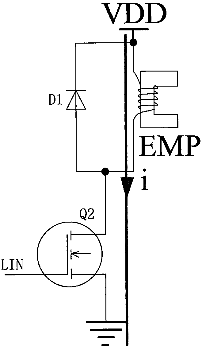
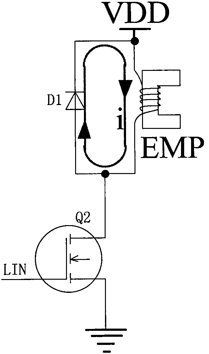
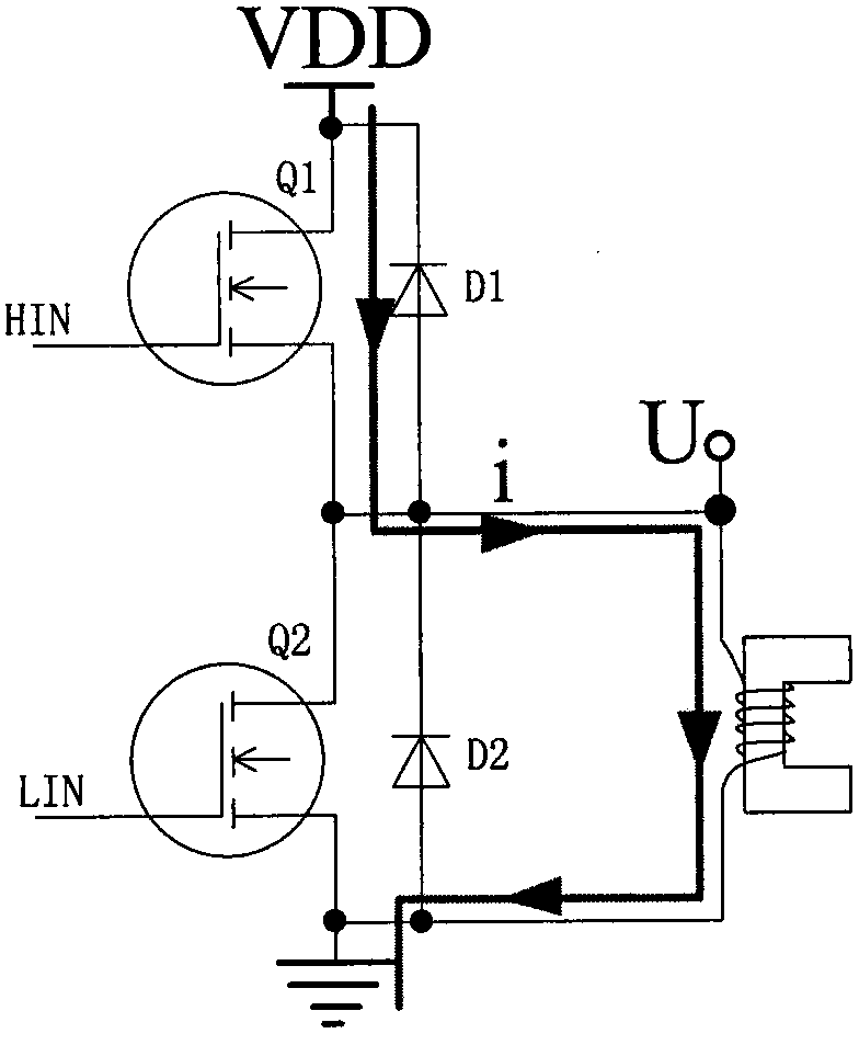
technical field [0001] The present invention relates to a PWM control technology, in particular to a magnetic force control method for an electromagnetic pole of a magnetic suspension bearing, and a current drive control technology for inductive loads. Background technique [0002] Figure 1-2 It is a circuit diagram of an inductive load drive. When the MOSFET switch signal LIN is high, Q2 is turned on, and the bus voltage is loaded on both ends of the electromagnetic pole EMP, resulting in figure 1 The driving current i shown, when LIN is low level, Q2 is closed, and the current i is as figure 2 As shown, the freewheeling through the diode D1 adjusts the magnitude of the current by adjusting the duty ratio of LIN. This control method has high conduction loss, and the switching frequency is restricted by the reverse recovery time of the freewheeling diode D1 and the switching loss. Generally only suitable for low power occasions. [0003] Figure 3-4 A low-voltage and h...

Claims


Application Information

Patent Timeline
Patent Type & Authority Patents(China)
IPC IPC(8): H02M1/088H02M3/158
CPCH02M1/088H02M3/158H02M1/0012H02M1/0041H02M1/0054H02M1/0064Y02B70/10
Inventor 张义兵殷理杰刘旺
Owner XIANGTAN UNIV
Why Eureka
Try Eureka