
Hardware-in-the-loop test system for charger

A technology for testing systems and chargers, which is applied in the electric power field and can solve problems such as inability to test the functions of chargers.

Active Publication Date: 2018-11-09
STATE GRID BEIJING ELECTRIC POWER +1
View PDF5 Cites 0 Cited by
  • Summary
  • Abstract
  • Description
  • Claims
  • Application Information

AI Technical Summary

Problems solved by technology

[0005] The main purpose of the present invention is to provide a hardware-in-the-loop test system for chargers to solve the problem that the hardware-in-the-loop test method in the related art cannot perform a functional test on the charger after it is connected to the power system

Method used


Image

  • Hardware-in-the-loop test system for charger
  • Hardware-in-the-loop test system for charger
  • Hardware-in-the-loop test system for charger

Examples


Embodiment Construction

[0021] It should be noted that, in the case of no conflict, the embodiments in the present application and the features in the embodiments can be combined with each other. The present invention will be described in detail below with reference to the accompanying drawings and examples.

[0022] In order to enable those skilled in the art to better understand the solution of the present application, the technical solution in the embodiment of the application will be clearly and completely described below in conjunction with the accompanying drawings in the embodiment of the application. Obviously, the described embodiment is only It is an embodiment of a part of the application, but not all of the embodiments. Based on the embodiments in this application, all other embodiments obtained by persons of ordinary skill in the art without creative efforts shall fall within the scope of protection of this application.

[0023] It should be noted that the terms "first" and "second" in ...


PUM


Abstract

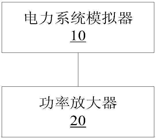
The invention discloses a hardware-in-loop test system of a battery charger. The system comprises an electric power system simulator and a power amplifier; the electric power system simulator is used for simulating an electric power system according to an electric power model of the electric power system and generating a simulation power grid signal, wherein the simulation power grid signal is an electric power signal outputted according to the electric power model; the power amplifier is connected with the electric power system simulator and the battery charger, and is used for executing power amplification according to the simulation power grid signal and producing a test voltage same with the power level of the battery charger, wherein the battery charger is used for executing a function test according to the test voltage. Due to the hardware-in-loop test system of the battery charger, the problem in the related technologies that a hardware-in-loop test method cannot execute a function test of a complete machine after the battery charger is switched in the electric power system is solved.

Description

technical field [0001] The invention relates to the field of electric power, in particular to a hardware-in-the-loop test system of a charger. Background technique [0002] The charger can be connected to the power system, and use the electric energy of the power system to charge and discharge the power electronic equipment. For example, after the electric vehicle is connected to the grid through the charger, the charger can charge the battery of the electric vehicle through the power provided by the grid. Alternatively, it is also possible to discharge the battery of the electric vehicle and feed the energy back to the grid. As the number of electric vehicles increases, the mutual influence of electric vehicles after they are connected to the grid will also deepen. ), are the hotspots and key issues of current research. The charger is a bridge for electric energy circulation between electric vehicles and the grid, and it is also an important component in the process of re...

Claims


Application Information

Patent Timeline
Patent Type & Authority Patents(China)
IPC IPC(8): G01R31/00
CPCG01R31/00
Inventor 焦然张宝群马龙飞宫成杨烁
Owner STATE GRID BEIJING ELECTRIC POWER
Learn More