A reactive power compensation optimal configuration method and reactive power compensation optimal configuration system

A technology that optimizes configuration and compensation capacity. It is used in reactive power compensation, circuit devices, AC network circuits, etc., and can solve problems such as difficulty in obtaining globally optimal compensation results.

Active Publication Date: 2018-08-24
ELECTRIC POWER RES INST OF GUANGDONG POWER GRID
View PDF2 Cites 0 Cited by
  • Summary
  • Abstract
  • Description
  • Claims
  • Application Information

AI Technical Summary

Problems solved by technology

[0005] In view of this, the present invention provides a reactive power compensation optimal configuration method and a reactive power compensation optimal configuration system to solve the problem that it is difficult to obtain a globally optimal compensation result in the prior art

Method used


Image

  • A reactive power compensation optimal configuration method and reactive power compensation optimal configuration system
  • A reactive power compensation optimal configuration method and reactive power compensation optimal configuration system
  • A reactive power compensation optimal configuration method and reactive power compensation optimal configuration system

Examples


Embodiment Construction

[0058] The technical solutions in the embodiments of the present invention will be clearly and completely described below in conjunction with the accompanying drawings in the embodiments of the present invention. Obviously, the described embodiments are only a part of the embodiments of the present invention, rather than all the embodiments. Based on the embodiments of the present invention, all other embodiments obtained by those of ordinary skill in the art without creative work shall fall within the protection scope of the present invention.

[0059] The present invention provides a reactive power compensation optimization configuration method to solve the problem that the prior art is difficult to obtain a global optimal compensation result.

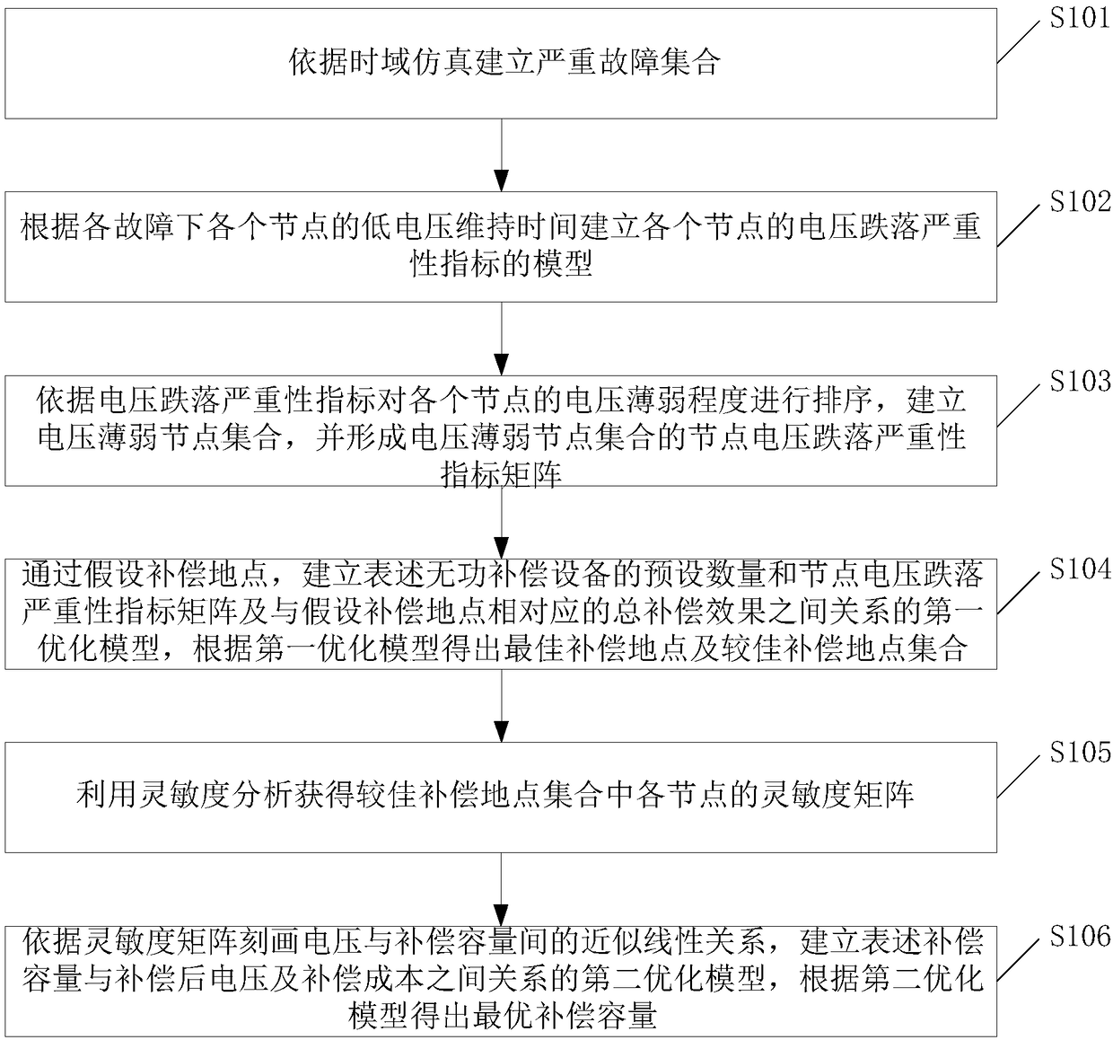
[0060] Specifically, the reactive power compensation optimization configuration method, such as figure 1 Shown, including:

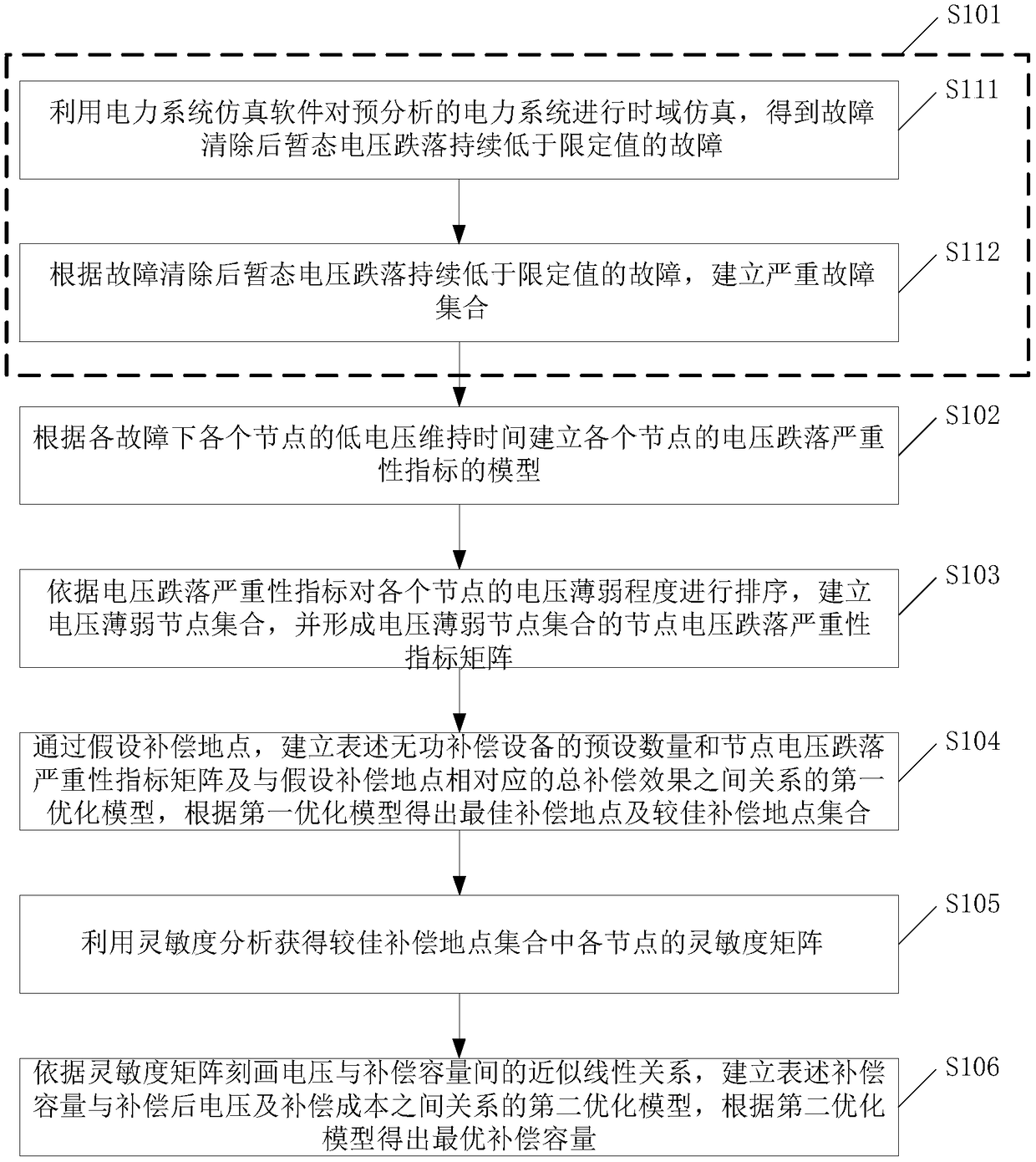
[0061] S101. Establish a serious fault set based on time domain simulation;

[0062] Specifically, the power system...


PUM


Abstract

The application provides a reactive power compensation optimizing configuration method and a reactive power compensation optimizing configuration system. A problem of transient voltage instability in an electric power system is solved from an angle of dynamic reactive power compensation according to low voltage maintenance time of each node in each fault condition. An optimal compensation place and optimal compensation capacity can be obtained via two optimizing models established by the reactive power compensation optimizing configuration method and the reactive power compensation optimizing configuration system, a global optimal compensation result is obtained, and system operation safety and stability are ensured.

Description

Technical field [0001] The invention relates to the technical field of power systems, and in particular to a reactive power compensation optimization configuration method and a reactive power compensation optimization configuration system. Background technique [0002] In recent years, multiple blackouts worldwide have been caused by voltage instability. Moreover, with the continuous improvement of the complexity and voltage level of the power grid, the increasing load and the continuous implementation of large AC and DC interconnected power grids, the problem of transient voltage instability after a fault occurs in the power system has become increasingly prominent. [0003] One of the key factors leading to transient voltage instability is the insufficient dynamic reactive power support of the power system. Although there are some studies on the optimal configuration of system reactive power compensation, most of them use static voltage stability analysis methods; For example, a...

Claims


Application Information

Patent Timeline
Patent Type & Authority Patents(China)
IPC IPC(8): H02J3/16
CPCH02J3/16H02J2203/20Y02E40/30
Inventor 张俊峰付聪赵艳军唐景星王钤翁洪杰安然然
Owner ELECTRIC POWER RES INST OF GUANGDONG POWER GRID
Why Eureka
Try Eureka