
An electric rotary drive for high row seats

A technology of electric rotation and drive, which is applied to seats, railway car body parts, transportation and packaging, etc., and can solve the problems of not installing electric rotation drives

Active Publication Date: 2017-12-19
湖北韵奥科技有限公司
View PDF7 Cites 0 Cited by
  • Summary
  • Abstract
  • Description
  • Claims
  • Application Information

AI Technical Summary

Problems solved by technology

[0003] At present, my country has not installed electric rotary drives on the high-row first-class and second-class seats.

Method used


Image

  • An electric rotary drive for high row seats
  • An electric rotary drive for high row seats
  • An electric rotary drive for high row seats

Examples


Embodiment Construction

[0014] Embodiments of the present invention will now be described with reference to the drawings, in which like reference numerals represent like elements.

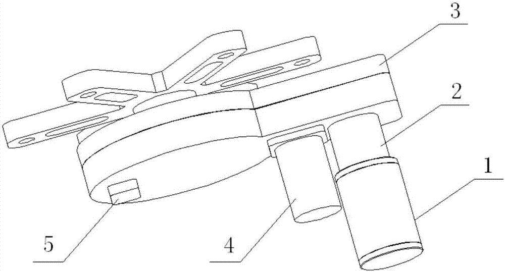
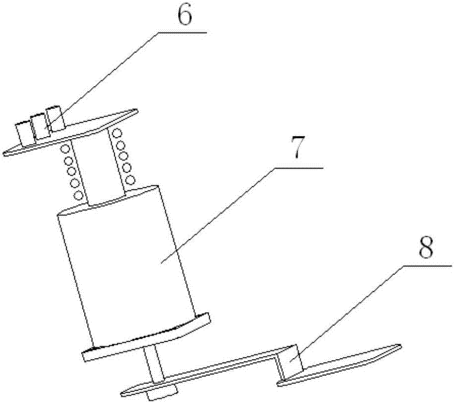
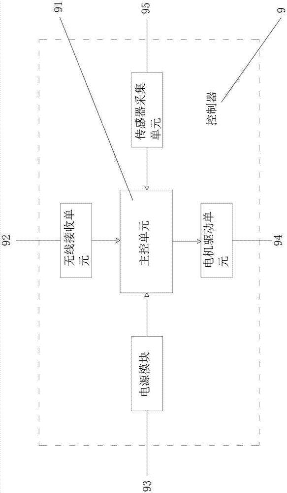
[0015] Please refer to Figure 1 to Figure 3 , an electric rotary driver for high-row seats, including a DC motor 1, a reducer 2, a transmission mechanism 3, a small electric clutch 4, a sensor 5, a large electric clutch 7 and a controller 9, and the transmission mechanism 3 is installed On the chair frame of the high-row seat; the output shaft of the DC motor 1 is connected in rotation with the transmission mechanism 3 through the reducer 2, and the small electric clutch 4 is installed on the transmission mechanism 3, and the small electric clutch 4 is small when it is not powered on. The electric clutch 4 and the transmission mechanism 3 are in the disengaged state and the two are in the combined state when the small electric clutch 4 is powered on, the sensor 5 is installed on the transmission mechanism 3, and the larg...


PUM


Abstract

The invention discloses an electric rotating driver for a seat on a high speed train. The electric rotating driver comprises a direct current motor, a speed reducer, a transmission mechanism, a small electric clutch, a sensor, a large electric clutch and a controller, wherein the transmission mechanism is arranged on a seat frame of the seat on the high speed train; the direct current motor is connected with the transmission mechanism through the speed reducer in a rotatable manner; the small electric clutch is arranged on the transmission mechanism; when the small electric clutch is not powered on, the small electric clutch and the transmission mechanism are separated; when the small electric clutch is powered on, the small electric clutch and the transmission mechanism are connected; the sensor is arranged on the transmission mechanism; the large electric clutch is connected with a clutch bracing wire of the seat on the high speed train and is mounted on a pedal clutch of the seat on the high speed train, and when powered on, the large electric clutch is separated from the seat frame of the seat on the high speed train; the controller is connected with the direct current motor, the sensor, the small electric clutch and the large electric clutch. The electric rotating driver provided by the invention achieves an effect of making the seat automatically turn in a remote control manner.

Description

technical field [0001] The invention relates to an electric rotary driver, in particular to an electric rotary driver used for high-row first-class and second-class seats and the like. Background technique [0002] A driver is a device that converts electrical control signals into mechanical actions. The drives can be air driven or hydraulic using pressure, or they can be powered by electricity. Electric rotary drives generally include motors, reducers, sensors, and controllers, etc., which can perform rotational motion around a specific axis. [0003] At present, my country has not yet installed electric rotary drives on high-row first-class and second-class seats. When the seat needs to be rotated, the conductor is required to manually adjust each seat in the compartment one by one. Therefore need a kind of electric rotary driver to go to realize the automatic steering of seat, to reduce the workload of conductor. Contents of the invention [0004] The purpose of the...

Claims


Application Information

Patent Timeline
Patent Type & Authority Patents(China)
IPC IPC(8): B61D33/00
CPCB61D33/0085
Inventor 刘娟
Owner 湖北韵奥科技有限公司
Learn More