Optical eyepiece lens and head-mounted display device
A technology of eyepiece and lens, which is applied in the field of head-mounted display equipment and its optical eyepiece lens, can solve the problems of product weight, large size, and high cost, and achieve the effects of improving user experience, excellent imaging quality, and good optical performance
- Summary
- Abstract
- Description
- Claims
- Application Information
AI Technical Summary
Problems solved by technology
Method used
Image

Examples
Embodiment 1
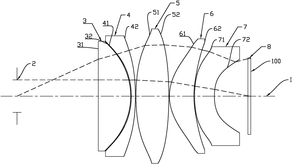
[0073] Such as figure 1 As shown, the optical eyepiece lens of this embodiment includes a diaphragm 2, a first lens 3, a second lens 4, a third lens 5, and a fourth lens in sequence from the image side to the object side along the optical axis I. Lens 6, a fifth lens 7 and a protective glass 8, the first lens 3, the second lens 4, the third lens 5, the fourth lens 6 and the fifth lens 7 all have refractive power, and respectively include a An image side facing the image side and allowing the imaging light to pass through, and an object side facing the object side and allowing the imaging light to pass through.
[0074] The aperture (aperture stop) 2 is an equivalent aperture, and the entity of this part may not be provided in practical applications. The aperture stop 2 is arranged on the optical axis I of the first lens 3 facing the image side, and is located The position of the exit pupil of the optical eyepiece lens. The protective glass 8 is arranged on the optical axis I...
Embodiment 2
[0091] Such as Figure 5 As shown, each lens structure of this embodiment is basically the same as Embodiment 1, the difference is that the optical parameters and aspheric coefficients of each lens of this embodiment are different from Embodiment 1, and the optical parameters of each lens of this embodiment and aspherical coefficients are shown in Table 3 and Table 4 respectively
[0092] Table three, each lens optical parameter data of the second embodiment
[0093]
[0094]
[0095] Table four, the aspherical parameters of the second embodiment
[0096] noodle
K
a2
a4
a6
a8
a10
a12
like profile 31
-
0
-
-
-
-
-
object side 32
-0.109
0
-9.22E-06
2.82E-07
2.74E-10
5.01E-12
4.86E-14
like side 41
-0.104
0
4.29E-05
-5.88E-08
8.06E-10
2.71E-12
5.45E-14
object side 42
89.795
0
-4.16E-05
-5.05E-09
-2.04E-10
-8.13E-13
1.04E-14
lik...
Embodiment 3
[0102] Such as Figure 9 As shown, each lens structure of this embodiment is basically the same as Embodiment 1, the difference is that the optical parameters and aspheric coefficients of each lens of this embodiment are different from Embodiment 1, and the optical parameters of each lens of this embodiment and aspheric coefficients are shown in Table 5 and Table 6 respectively
[0103] Table five, each lens optical parameter data of the third embodiment
[0104]
[0105]
[0106] Table six, aspherical parameters of the third embodiment
[0107] noodle
K
a2
a4
a6
a8
a10
a12
like profile 31
-
0
-
-
-
-
-
object side 32
0.077
0
2.30E-05
-3.17E-08
-4.52E-10
-1.79E-12
2.16E-14
like side 41
0.383
0
-1.63E-05
3.46E-08
-2.88E-10
-4.31E-13
1.71E-14
object side 42
5.337
0
-3.77E-05
2.68E-08
3.19E-10
-3.55E-13
7.95E-17
like profile 5...
PUM
 Abstract
Description
Claims
Application Information
 - Generate Ideas
- Intellectual Property
- Life Sciences
- Materials
- Tech Scout
- Unparalleled Data Quality
- Higher Quality Content
- 60% Fewer Hallucinations
Browse by: Latest US Patents, China's latest patents, Technical Efficacy Thesaurus, Application Domain, Technology Topic, Popular Technical Reports.
© 2025 PatSnap. All rights reserved.Legal|Privacy policy|Modern Slavery Act Transparency Statement|Sitemap|About US| Contact US: help@patsnap.com