Gas-saving structure for pipeline argon arc welding

A technology for argon arc welding and pipelines is applied in the field of gas-saving structures for argon arc welding of pipelines, which can solve the problems of air leakage in sealed spaces, inconvenient pipeline placement, indeterminate shrinking shapes, etc., so as to reduce welding costs, shorten welding construction period, Argon saving effect

Active Publication Date: 2018-03-20
CHINA 19TH METALLURGICAL CORP
View PDF8 Cites 0 Cited by
  • Summary
  • Abstract
  • Description
  • Claims
  • Application Information

AI Technical Summary

Problems solved by technology

However, the airbag needs to be filled before it can play a sealing role, and filling the airbag requires a large amount of argon gas, and the inflation time is long; and the shrinkage shape of the airbag after deflation is indeterminate, which is not convenient to place in the pipeline. Once the airbag is placed in an improper position in the pipeline , it is easy to cause air leakage in the sealed space. What's more, the two airbags are connected by flexible connecting pipes. It is inconvenient to make the two airbags located on both sides of the welding seam

Method used


Image

  • Gas-saving structure for pipeline argon arc welding
  • Gas-saving structure for pipeline argon arc welding
  • Gas-saving structure for pipeline argon arc welding

Examples


Embodiment Construction

[0018] Below in conjunction with accompanying drawing and embodiment the present invention is described further as follows:

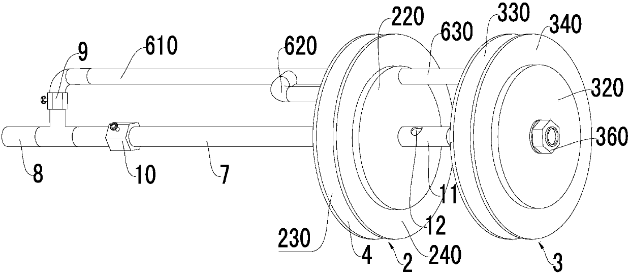
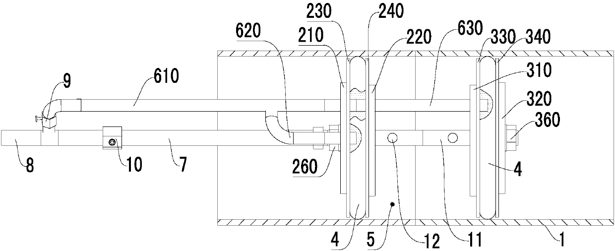
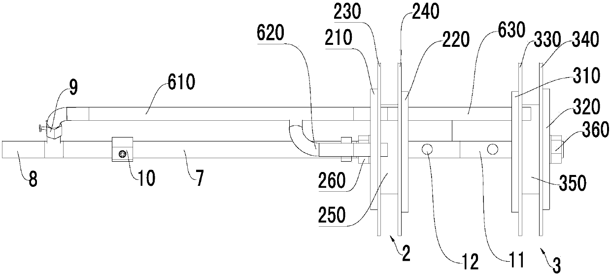
[0019] Such as figure 1 , figure 2 and image 3 As shown, a gas-saving structure for pipeline argon arc welding, including a pipeline 1 and a gas-saving device; Connector with the second blocking member 3; the outer circumference of the first blocking member 2 and the second blocking member 3 is surrounded by a circle of air bags 4; the air bag 4 is installed with an inflation pipeline communicated with the air bag 4; A gas delivery pipe 7 is installed on the first blocking member 2 and the second blocking member 3; the first blocking member 2 and the second blocking member 3 are located in the pipeline 1; the outer periphery of the air bag 4 is against the inner wall of the pipeline 1 ; The inner wall of the pipeline 1 between the first blocking member 2, the second blocking member 3, the air bag 4 and the first blocking member 2 and the second blo...


PUM


Abstract

The invention discloses a gas saving structure for pipeline argon arc welding, and belongs to the field of welding devices. The gas saving structure comprises a pipeline and a gas saving device, wherein the gas saving device comprises a first plugging member, a second plugging member and a connecting member for connecting the first plugging member with the second plugging member; the periphery of the first plugging member, as well as the periphery of the second plugging member, is surrounded by a circle of airbag; a gas supply pipeline which is communicated with the airbags is provided; a gas conveying tube is mounted on the first plugging member and the second plugging member; the first plugging member and the second plugging member are positioned inside the pipeline; the peripheries of the airbags are propped against the pipeline wall; the first plugging member, the second plugging member and the pipeline wall among the first plugging member, the second plugging member and the airbags form a sealed space; the gas conveying pipeline is arranged in the axial direction of the pipeline and is communicated with the sealed space; the gas supply pipeline is arranged along the pipeline. By adopting the gas saving structure for pipeline argon arc welding, argon for pipeline welding can be saved, the welding period can be shortened, the welding expense can be reduced, and due to adoption of the plugging members, the rigidity of the gas saving structure is improved, and the gas saving structure can be relatively well matched with the pipeline.

Description

technical field [0001] The invention belongs to the field of welding devices, in particular to a gas-saving structure for pipeline argon arc welding. Background technique [0002] To weld the pipeline by argon arc welding, it is necessary to fill the welding area inside the pipeline with argon gas to isolate the air from the welding area. At present, the non-welded port of the pipeline to be welded is usually sealed with a sealing plate, and the inner wall of the pipeline between the sealing plate and the sealing plate jointly forms an air-filled space. However, due to the large inflatable space, the consumption of argon gas is large, and the inflatable time is long, thereby prolonging the welding period. The application number is 201220532264.8, and the name is an inflatable sealing device for argon arc welding of stainless steel pipes. It discloses a sealing device, which includes two air bags, one of which has an inflatable tube and communicates with the other air bag. ...

Claims


Application Information

Patent Timeline
Patent Type & Authority Patents(China)
IPC IPC(8): B23K9/16B23K9/32
CPCB23K9/16B23K9/325
Inventor 孟晓宏
Owner CHINA 19TH METALLURGICAL CORP
Why Eureka
Try Eureka