Wing interior supporting structure of unmanned aerial vehicle

An internal support, UAV technology, applied in the direction of wings, unmanned aerial vehicles, motor vehicles, etc., can solve the influence of wing rudder surface effect, increased tremor, and increased influence of UAV flight stability, etc. problem, to achieve the effect of ensuring flight stability and flight speed, and reducing tremor

Active Publication Date: 2016-06-08
江西省山宜智能装备有限公司
View PDF7 Cites 2 Cited by
  • Summary
  • Abstract
  • Description
  • Claims
  • Application Information

AI Technical Summary

Problems solved by technology

[0003] Wing related technology is one of the core issues in the development of UAV technology. Most of the existing UAV wings use a single beam design. This design is simple in structure and light in weight, but its advantages are only reflected in the application on the wing. On a UAV with a small span, when the wingspan exceeds 1.5m and the wing width exceeds 0.25m, the tremor generated by the internal support structure of the wing with a single beam design will gradually increase during flight, which will affect the flight stability of the UAV. The impact will gradually increase
[0004] Therefore, designers began to adopt double-beam design for some large drones, but the simple use of double-beam design can effectively reduce the vibration of the wing, but at the same time it will obviously increase the weight of the wing, and at the same time affect the rudder surface of the wing. effect, thus affecting the flying speed and control stability of the UAV

Method used


Image

  • Wing interior supporting structure of unmanned aerial vehicle
  • Wing interior supporting structure of unmanned aerial vehicle
  • Wing interior supporting structure of unmanned aerial vehicle

Examples


Embodiment 1

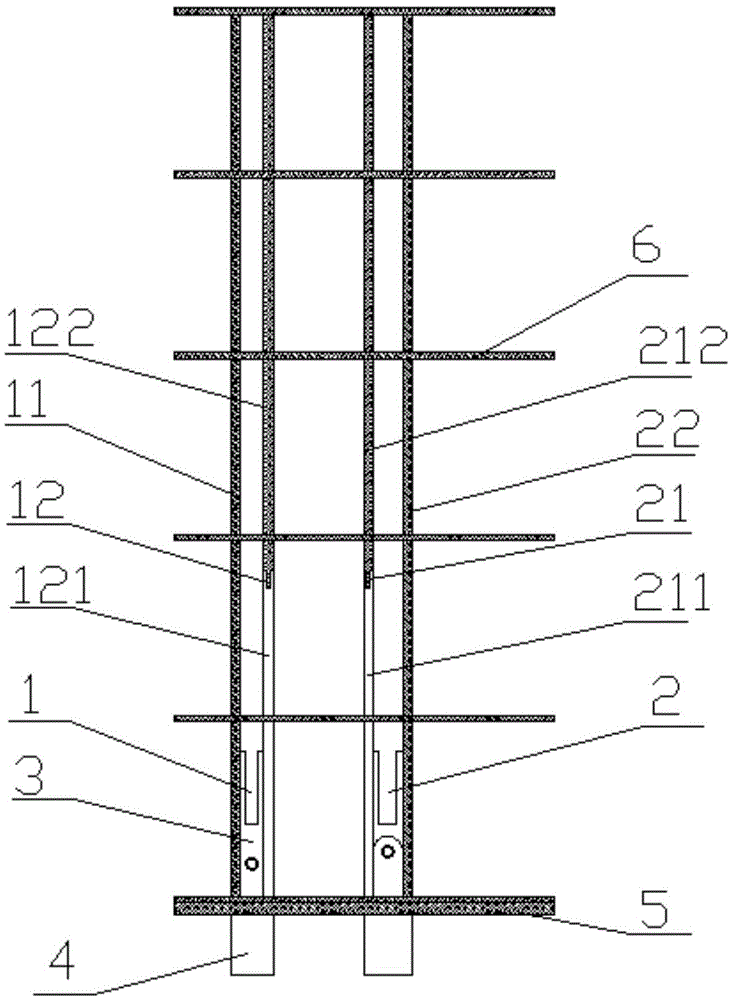
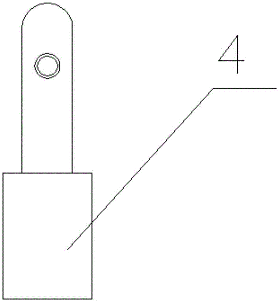
[0050] figure 1 It is a top view of Embodiment 1 of the present invention, figure 2 It is the left side view of Embodiment 1 of the present invention, image 3 It is a schematic diagram of a fuselage connector part according to an embodiment of the present invention, Figure 4It is a schematic diagram of the connecting baffle part of the present invention, as shown in the figure: a kind of unmanned aerial vehicle wing internal support structure, including front beam 1, rear beam 2, connecting baffle plate 5 and 6 support plates 6; the front beam 1 includes a front beam outer bar 11 and a front beam inner bar 12, and a beam connector 3 is provided between the front beam outer bar 11 and the front beam inner bar 12; the rear beam 2 includes a rear beam outer bar 22 and a rear beam The inner rod 21, the outer rod 22 of the rear beam and the inner rod 21 of the rear beam are provided with a beam connector 3; the inner rod 12 of the front beam includes a metal rod 111 of the inn...

Embodiment 2

[0059] Figure 4 It is a schematic diagram of the connecting baffle part of the present invention, Figure 5 It is a top view of Embodiment 2 of the present invention, Figure 6 It is the left view of Embodiment 2 of the present invention, Figure 7 It is a schematic diagram of the support plate part of the second embodiment of the present invention, as shown in the figure: an internal support structure of an unmanned aerial vehicle wing, including a front beam 1, a rear beam 2, a connecting baffle 5 and 8 support plates 6; The front beam 1 includes a front beam outer bar 11 and a front beam inner bar 12, and a beam connector 3 is arranged between the front beam outer bar 11 and the front beam inner bar 12; the rear beam 2 includes a rear beam outer bar 22 and the rear beam inner rod 21, the rear beam outer rod 22 and the rear beam inner rod 21 are provided with a beam connector 3; the front beam inner rod 12 includes a front beam inner rod metal rod 121 and a front beam inn...


PUM


Abstract

The invention aims to provide a wing interior supporting structure of an unmanned aerial vehicle. The wing interior supporting structure of the unmanned aerial vehicle comprises a front transverse beam, a rear transverse beam, a connecting baffle and a plurality of supporting plates. The front transverse beam comprises a front transverse beam outer rod and a front transverse beam inner rod, and the rear transverse beam comprises a rear transverse beam outer rod and a rear transverse beam inner rod. The front transverse beam inner rod comprises a front transverse beam inner rod metal rod and a front transverse beam inner rod composite rod. The rear transverse beam inner rod comprises a rear transverse beam inner rod metal rod and a rear transverse beam inner rod composite rod. The front transverse beam and the rear transverse beam are arranged in parallel. Any one supporting plate is perpendicular to the front transverse beam and is movably connected with the front transverse beam. Any one supporting plate is movably connected with the rear transverse beam. The connecting baffle is provided with a front connecting through hole and a rear connecting through hole. The wing interior supporting structure of the unmanned aerial vehicle has the beneficial effects that by means of the two transverse beam structures each of which is made of metal and a composite material in combination, vibration of a wing interior structure in the flying process of the unmanned aerial vehicle is reduced and the flying stability and flying speed are guaranteed on the premise that the strength is guaranteed and the whole wing weight is not markedly increased.

Description

technical field [0001] The invention relates to the field of unmanned aerial vehicle manufacturing, in particular to an internal support structure for the wing of an unmanned aerial vehicle. Background technique [0002] With the improvement of the overall technology of the drone industry, the application field of drones is constantly expanding, people's requirements for drones are getting higher and higher, and the technology of large-size and wide-wingspan drones is gradually mature. [0003] Wing related technology is one of the core issues in the development of UAV technology. Most of the existing UAV wings use a single beam design. This design is simple in structure and light in weight, but its advantages are only reflected in the application on the wing. On a UAV with a small span, when the wingspan exceeds 1.5m and the wing width exceeds 0.25m, the tremor generated by the internal support structure of the wing with a single beam design will gradually increase during f...

Claims


Application Information

Patent Timeline
Patent Type & Authority Applications(China)
IPC IPC(8): B64C3/18B64C3/22
CPCB64C3/182B64C3/185B64C3/187B64C3/22B64U10/25
Inventor 王若潭
Owner 江西省山宜智能装备有限公司
Why Eureka
Try Eureka