Ship propulsion mechanism

A technology of propulsion mechanism and ship, applied in the direction of rotary propeller, rotary propeller, etc., can solve problems such as inability to adapt to various propeller speeds, poor elimination of hub eddy current, etc., to achieve high practical value, increase propulsion efficiency, and improve propulsion The effect of efficiency

Inactive Publication Date: 2016-06-08
ZHEJIANG OCEAN UNIV
View PDF14 Cites 7 Cited by
  • Summary
  • Abstract
  • Description
  • Claims
  • Application Information

AI Technical Summary

Problems solved by technology

[0003] The present invention solves the problem that the prior art ship propulsion mechanism has poor hub vortex elimination effect and cannot adapt to various propeller speeds, and provides a ship propulsion mechanism that can effectively reduce the hub vortex within a certain propeller speed range

Method used


Image

  • Ship propulsion mechanism
  • Ship propulsion mechanism
  • Ship propulsion mechanism

Examples


Embodiment 1

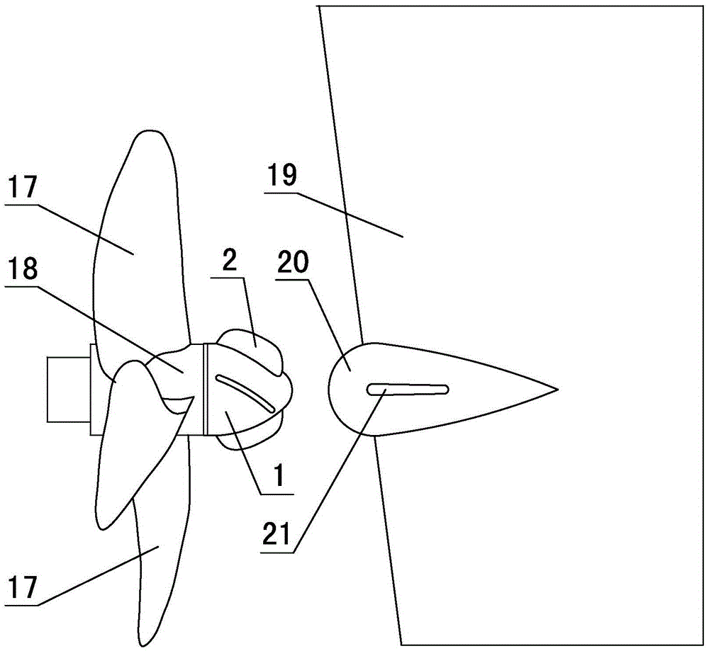
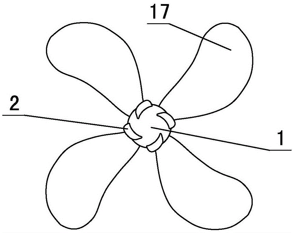
[0028] in such as figure 1 , figure 2 , image 3 In shown embodiment 1, 1. a kind of ship propulsion mechanism comprises propeller and ship rudder, and described propeller comprises propeller hub 18 and 4 blades 17, and propeller hub is provided with propeller cap, and propeller cap shell The diameter of the installation end of the rudder is equal to the diameter of the propeller hub, and the relative position of the rudder 19 and the propeller cap is provided with a rudder ball 20, and the diameter of the rudder ball is 1.2 times of the maximum diameter of the propeller cap shell, and the rear part of the rudder ball Gradually shrink to form a tapered structure, two booster wings 21 are arranged on both sides of the rudder ball in the horizontal direction, symmetrically arranged on both sides of the rudder ball, the height of the booster wings is 40% of the diameter of the rudder ball, and the length of the booster wings The degree is 1.2 times the diameter of the rudder b...

Embodiment 2

[0032] The limiting grooves of embodiment 2 are 5 straight grooves, and the center line of the limiting groove and the line between the two ends of the limiting groove and the center of rotation of the fixed plate form an obtuse triangle (see Figure 8 ), the outer edge of the fin plate is provided with a side strip 13 with a circular cross section (see Figure 9 ), the diameter of the side bar is 3 times the thickness of the fin plate, and the rest are the same as in Example 1.

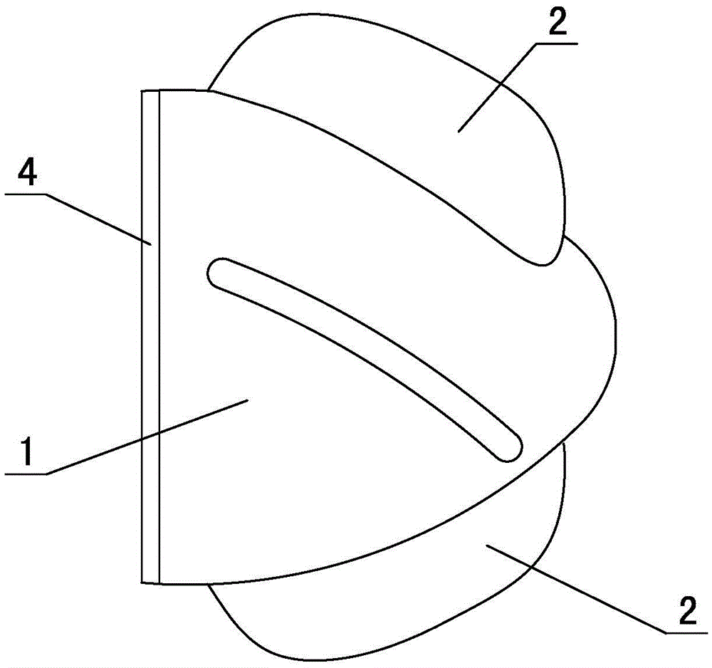
[0033] The fin plate of the propeller hub cap of the present invention is provided with a rotating shaft, and the rotating shaft is connected with a deflection mechanism. When the rotation speed of the propeller is different, the deflection mechanism can provide different deflection angles, so that the helix angle of the fin plate can be adjusted automatically according to the rotation speed of the propeller. Adjustment, thereby solving the problem that the fixed fin plate on the propeller cap of the...


PUM


Abstract

The invention discloses a ship propulsion mechanism. The ship propulsion mechanism comprises a propeller and a rudder. A propeller hub is provided with a propeller hub cap. A rudder ball is arranged in the position, opposite to the propeller hub cap, of the rudder. Boosting wings are arranged on the two sides of the horizontal direction of the rudder ball correspondingly. The propeller hub cap comprises a propeller hub cap shell and fin keels. The fin keels are connected with a rotary shaft which is connected with a fin keel deflection mechanism. A fixing plate is arranged at the installation end of the propeller hub cap and provided with limiting grooves. The fin keel deflection mechanism comprises deflection rods. One ends of the deflection rods are connected with the rotary shaft, and the other ends of the deflection rods are each provided with an inertia ball adaptively arranged in the corresponding limiting groove. Reset springs are further arranged between the deflection rods and the propeller hub cap shell. Through the ship propulsion mechanism, the problems that in the prior art, a hub of a ship propulsion mechanism is poor in eddy elimination function, and the ship propulsion mechanism cannot adapt to the propeller speed of various propellers are effectively solved. Through the structure of the ship propulsion mechanism, hub eddies can be effectively reduced within a certain propeller speed range of the propeller, the propulsion efficiency of the propeller is improved, and very high practical value is achieved.

Description

technical field [0001] The invention relates to the technical field of ship manufacturing, in particular to a ship propulsion mechanism capable of improving propulsion efficiency. Background technique [0002] Ships in the prior art are usually driven by propellers, and the propulsion generated by the rotation of the propellers installed at the lower part of the stern makes the ships move. However, when the propeller rotates, a strong hub vortex will be generated behind the propeller hub, causing cavitation tendency behind the hub, and the hub vortex will reduce the efficiency of the ship propeller and cause vibration and noise at the propeller. In order to solve this problem and improve the propulsion efficiency of the propeller, some people use counter-rotating propellers to reduce the hub vortex, and some people add fins to the propeller hub cap to reduce the hub vortex, disperse and reduce the concentrated on the hub cap Hub vortex cavitation. The publication date is M...

Claims


Application Information

Patent Timeline
Patent Type & Authority Applications(China)
IPC IPC(8): B63H1/28B63H1/18
CPCB63H1/28B63H1/18
Inventor 陈正寿程枳宁赵陈张兆德
Owner ZHEJIANG OCEAN UNIV
Why Eureka
Try Eureka