
Electrifying device of railway logistics electric car

A technology of electric trolley and power-taking device, which is applied in the direction of transportation and packaging, conveyors, mechanical conveyors, etc. It can solve the problems that the switching power supply cannot be loaded at the same time, the power supply cannot meet the actual needs, and the entire system can work at the same time. Short, to avoid mutual interference, to ensure the effect of normal operation

Inactive Publication Date: 2016-06-01
苏州威特凌科自动化系统有限公司
View PDF10 Cites 5 Cited by
  • Summary
  • Abstract
  • Description
  • Claims
  • Application Information

AI Technical Summary

Problems solved by technology

In order to use safely, the voltage on the power signal track is best to use a 24V low-voltage DC power supply. The DC24V power supply has strict requirements on the transmission distance, because the long-distance power transmission will have a large voltage drop, which will affect the normal operation of the circuit. Moreover, the power of the switching power supply cannot load the entire system at the same time, and the transmission distance of modern logistics systems often reaches thousands of meters, so a single DC24V power supply is far from meeting the actual needs. At the same time, the command signals obtained in different areas of the logistics system are often different. , there are often multiple signal sources, an electric car moves to different areas, the power supply and signal source need to be obtained separately, and it is required to be uninterrupted
It is difficult for the electric trolleys on the existing rail logistics system to meet the above requirements

Method used


Image

  • Electrifying device of railway logistics electric car
  • Electrifying device of railway logistics electric car
  • Electrifying device of railway logistics electric car

Examples


Embodiment Construction

[0016] The implementation of the present invention will be illustrated by specific specific examples below, and those skilled in the art can easily understand other advantages and effects of the present invention from the contents disclosed in this specification.

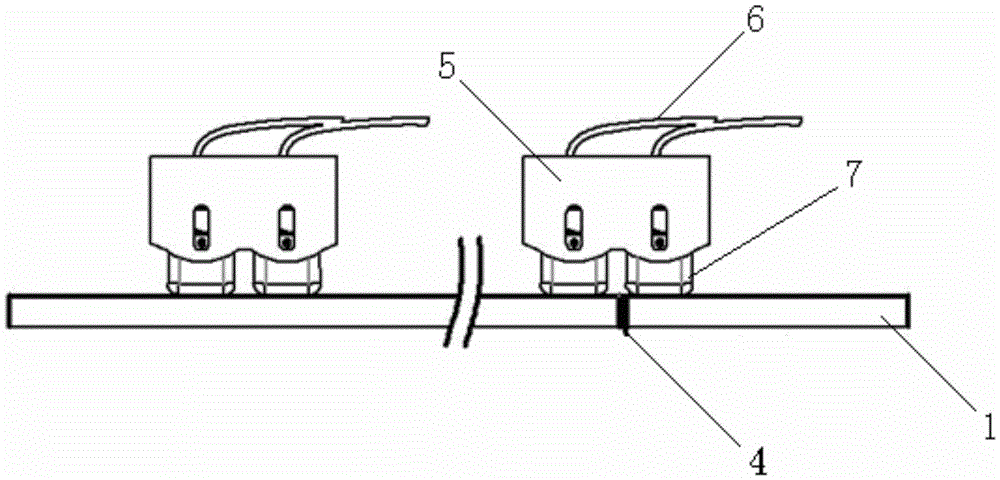
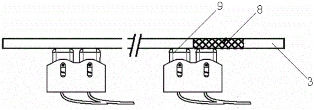
[0017] see Figure 1 to Figure 5 . It should be noted that the structures, proportions, sizes, etc. shown in the drawings attached to this specification are only used to match the content disclosed in the specification, for those who are familiar with this technology to understand and read, and are not used to limit the implementation of the present invention. Limiting conditions, so there is no technical substantive meaning, any modification of structure, change of proportional relationship or adjustment of size, without affecting the effect and purpose of the present invention, should still fall within the scope of the present invention. The disclosed technical content must be within the scope covered. At the sa...


PUM


Abstract

The invention provides an electrifying device of a railway logistics electric car. A power supply signal wire of the electrifying device consists of multiple power supply signal guide rails; power supply partition insulation blocks are arranged between two adjacent power supply signal guide rails; each set of power supply signal electric brushes on the electric car includes front and back two electric brushes; and the distance between the two electric brushes is larger than the length of the power supply partition insulation blocks, so that the power supply quality of the electric car can be effectively guaranteed. A control signal wire of the electrifying device consists of multiple control signal guide rails; signal partition insulation blocks are arranged between two adjacent control signal guide rails; each set of control signal electric brushes on the electric car includes front and back two electric brushes; and the distance between the two electric brushes is larger than the length of the signal partition insulation blocks, so that mutual interference of command signals in different areas can be prevented, and normal operation of the electric car is guaranteed.

Description

technical field [0001] The invention relates to a rail logistics system, in particular to a power-taking device for an electric trolley in the rail logistics system. Background technique [0002] The logistics transmission system refers to a transmission system that transports items in a set area with the help of a series of technologies and facilities such as information technology, photoelectric technology, and mechanical transmission. With the advancement of technology, various logistics transmission systems are widely used in airports, shopping malls, banks, factories, libraries and other fields. With the development of information technology, the automation of logistics transmission systems is also getting higher and higher. A new period of development. The logistics transmission system is widely welcomed because it can greatly improve efficiency and save manpower, and its application field has gradually expanded to the medical field. The main function of the hospital...

Claims


Application Information

Patent Timeline
Patent Type & Authority Applications(China)
IPC IPC(8): B65G35/00
CPCB65G35/00
Inventor 张书阳姚勇李培培张冬林徐金星
Owner 苏州威特凌科自动化系统有限公司
Learn More