


Quick Research
Generate reliable direction feasibility study reports for your R&D in just a few steps.

Technical Q&A
Discover and master advanced knowledge NOW. Basics, ideas, possibilities, all at once.

Find Solutions
As an expert in R&D theories, this can generate solutions to your technical problems instantly.

Evaluate Feasibility
Analyze your overall solution with one click, know your potential R&D risks in advance.

Monitor Landscape
Get weekly tech updates, stay abreast of the latest tech innovations and key insights.
Work method of quickly-expanded type vehicle-mounted tent
A working method, unfolding technology, applied in tents/canopies, building types, buildings, etc., can solve problems such as troublesome operation, and achieve the effect of easy opening
- Summary
- Abstract
- Description
- Claims
- Application Information
AI Technical Summary
Problems solved by technology
Method used
Image

Examples
Embodiment 1
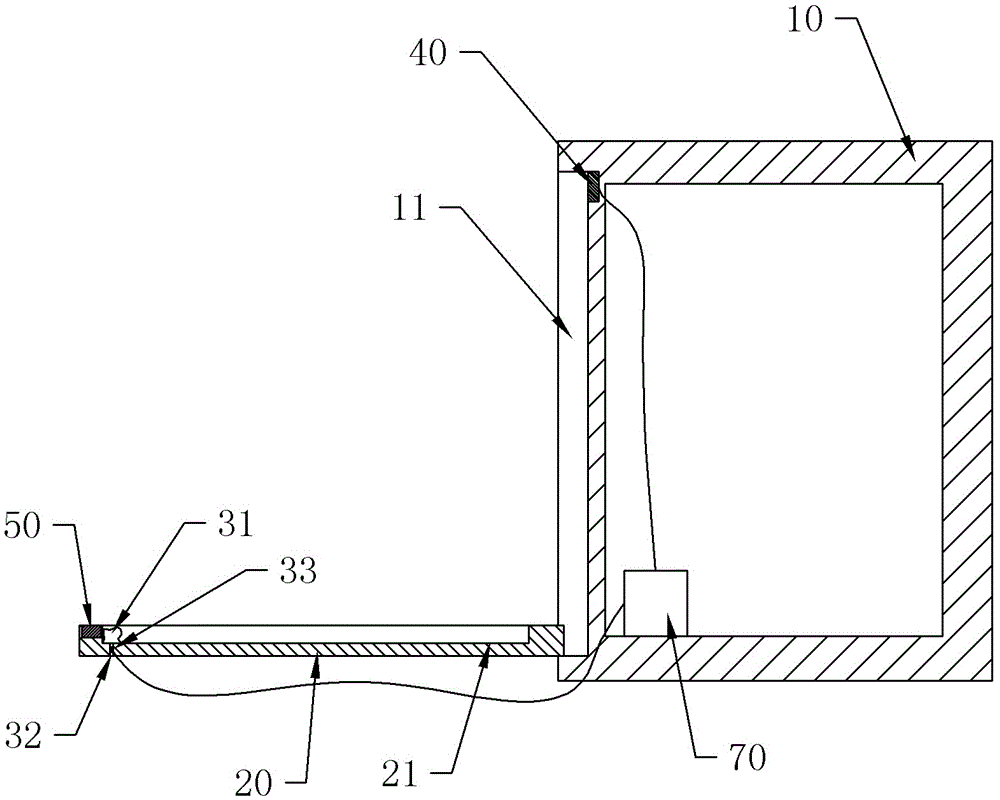
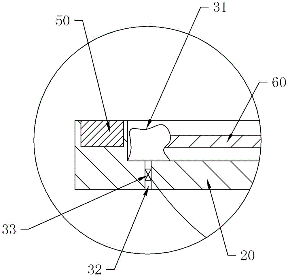
[0021] Embodiment 1 is basically as attached figure 1 Shown: a kind of working method of quick-deployable vehicle-mounted tent, comprises support plate 20, inflatable support frame, tarpaulin, cushioning air bag 31 and controller 70, one side of support plate 20 is hinged on the lower part of compartment 10 side, cushions The airbag 31 is connected on the support plate 20, and the buffer airbag 31 is provided with an exhaust nozzle 32 towards the outside of the support plate 20, and an electric control valve 33 is installed on the exhaust nozzle 32; A first retractable groove 11 is provided, and a second retractable groove 21 is provided on the support plate 20. The inflatable support frame is connected in the second retractable groove 21, and the tarpaulin covers the inflatable support frame; the first retractable Electromagnet 40 is provided in groove 11, and support plate 20 is provided with the magnet 50 that cooperates to absorb or repel electromagnet 40, and the magnet 5...
Embodiment 2
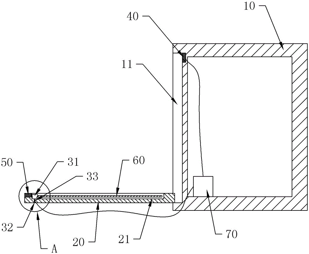
[0027] Such as figure 2 with 3 As shown, the difference from Embodiment 1 is that the support plate 20 is provided with a cover plate 60 that is slidably connected to it and can cover the second receiving groove 21, and the cover plate 60 can slide until the support plate 20 is away from the compartment. The edge on one side of 10 is reversed, and the specific structure is as follows: the two sides of the support plate 20 are provided with chute and sliding hole, the cover plate 60 is slidably connected with the chute, and the two ends of the cover plate 60 near the hinged side of the support plate 20 are provided with Insert the slide pin into the slide hole.
[0028] Step 1 also includes the following steps: receiving the inflatable support frame and the tarpaulin in the second storage groove 21, sliding the cover plate 60, and sliding the two sides of the cover plate 60 in the chute, and placing the inflatable support frame and the tarpaulin cover Combined in the second ...
Embodiment 3
[0031] The difference from Embodiment 2 is that: the support plate 20 is provided with a first positioning hole on the side away from the hinge, and the cover plate 60 is provided with a second positioning hole matching the first positioning hole.
[0032] After step 3, the following steps are included: slide the cover plate 60 to the outside of the support plate 20, turn over the cover plate 60, align the first positioning hole with the second positioning hole, and insert the positioning pin. After being positioned by the positioning pin and the positioning hole, the cover plate 60 cannot be overturned, so that the cover plate 60 can stably support the bottom plate.
PUM
 Abstract
Description
Claims
Application Information
 - R&D Engineer
- R&D Manager
- IP Professional
- Industry Leading Data Capabilities
- Powerful AI technology
- Patent DNA Extraction
Browse by: Latest US Patents, China's latest patents, Technical Efficacy Thesaurus, Application Domain, Technology Topic, Popular Technical Reports.
© 2024 PatSnap. All rights reserved.Legal|Privacy policy|Modern Slavery Act Transparency Statement|Sitemap|About US| Contact US: help@patsnap.com