


Quick Research
Generate reliable direction feasibility study reports for your R&D in just a few steps.

Technical Q&A
Discover and master advanced knowledge NOW. Basics, ideas, possibilities, all at once.

Find Solutions
As an expert in R&D theories, this can generate solutions to your technical problems instantly.

Evaluate Feasibility
Analyze your overall solution with one click, know your potential R&D risks in advance.

Monitor Landscape
Get weekly tech updates, stay abreast of the latest tech innovations and key insights.
A Continuously Adjustable Bubble-Driven Valveless Micropump
An adjustable, micro-pump technology, applied in the direction of variable capacity pump components, pumps, pump components, etc., can solve the problems of inability to continuously adjust, low efficiency, large flow pulsation, etc., achieve stable power, low heat radiation, increase The effect of large pumping flow
- Summary
- Abstract
- Description
- Claims
- Application Information
AI Technical Summary
Problems solved by technology
Method used
Image

Examples
Embodiment 1
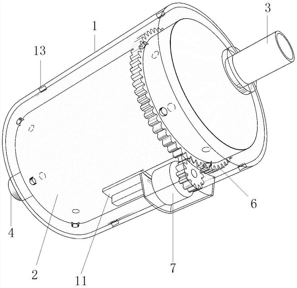
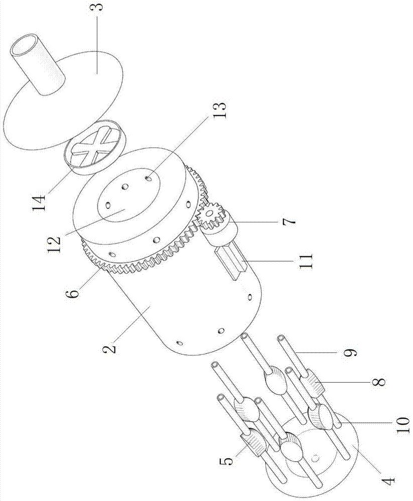
[0021] Such as Figure 1-2 As shown, a continuously adjustable bubble-driven valveless micropump includes a pump casing 1, a circular tubular pump core 2 installed in the pump casing 1, an integrated input tube shaft 3 installed at the left end of the circular tubular pump core 2, and a The integrated output tube shaft 4 at the right end of the tubular pump core 2, six micropump units 5 evenly arranged on the inner side wall of the tubular pump core 2; The end surface is connected to the rotating shaft; the outer surface of the tubular pump core 2 is provided with a drive gear 6, and the outside of the pump casing 1 is installed with a drive motor 7 whose output end meshes with the drive gear 6; the micropump unit 5 includes a heat-driven pump chamber 8 located in the middle , the suction passage 9 located at the left end of the heat-driven pump chamber 8 and connected with the heat-driven pump chamber 8, the discharge passage 10 located at the right end of the heat-driven pum...
Embodiment 2
[0024] The difference between this embodiment and Embodiment 1 is that: the inner wall of the pump casing 1 is equipped with an electromagnetic heating circuit corresponding to the position of the heat-driven pump chamber 8, and the electromagnetic heating circuit consists of a power supply, a switch connected in series in the circuit, an adjustable resistor, The magnetic induction coil is formed; the position of the magnetic induction coil is matched with the heat-driven pump chamber 8; the outer wall of the heat-driven pump chamber 8 is made of ferritic stainless steel.
[0025] In this embodiment, the outer wall of the heat-driven pump chamber 8 is made of ferritic stainless steel with good magnetic conductivity. The purpose is to cooperate with the principle of the electromagnetic heating circuit and use eddy current to achieve heating. The electromagnetic heating circuit has a shorter reaction time than resistance heating. , the local heating speed is fast, the influence o...
PUM
 Abstract
Description
Claims
Application Information
 - R&D Engineer
- R&D Manager
- IP Professional
- Industry Leading Data Capabilities
- Powerful AI technology
- Patent DNA Extraction
Browse by: Latest US Patents, China's latest patents, Technical Efficacy Thesaurus, Application Domain, Technology Topic, Popular Technical Reports.
© 2024 PatSnap. All rights reserved.Legal|Privacy policy|Modern Slavery Act Transparency Statement|Sitemap|About US| Contact US: help@patsnap.com