


Quick Research
Generate reliable direction feasibility study reports for your R&D in just a few steps.

Technical Q&A
Discover and master advanced knowledge NOW. Basics, ideas, possibilities, all at once.

Find Solutions
As an expert in R&D theories, this can generate solutions to your technical problems instantly.

Evaluate Feasibility
Analyze your overall solution with one click, know your potential R&D risks in advance.

Monitor Landscape
Get weekly tech updates, stay abreast of the latest tech innovations and key insights.
Method and device for measuring direct current electron beam trajectory
A technology of measuring device and electron beam, which is applied in the direction of measuring device, radiation measurement, particle motion recording, etc., can solve the problem of inability to measure DC electron beam, and achieve the effect of improving measurement efficiency and avoiding repeated loading and unloading.
- Summary
- Abstract
- Description
- Claims
- Application Information
AI Technical Summary
Problems solved by technology
Method used
Image

Examples
Embodiment 1
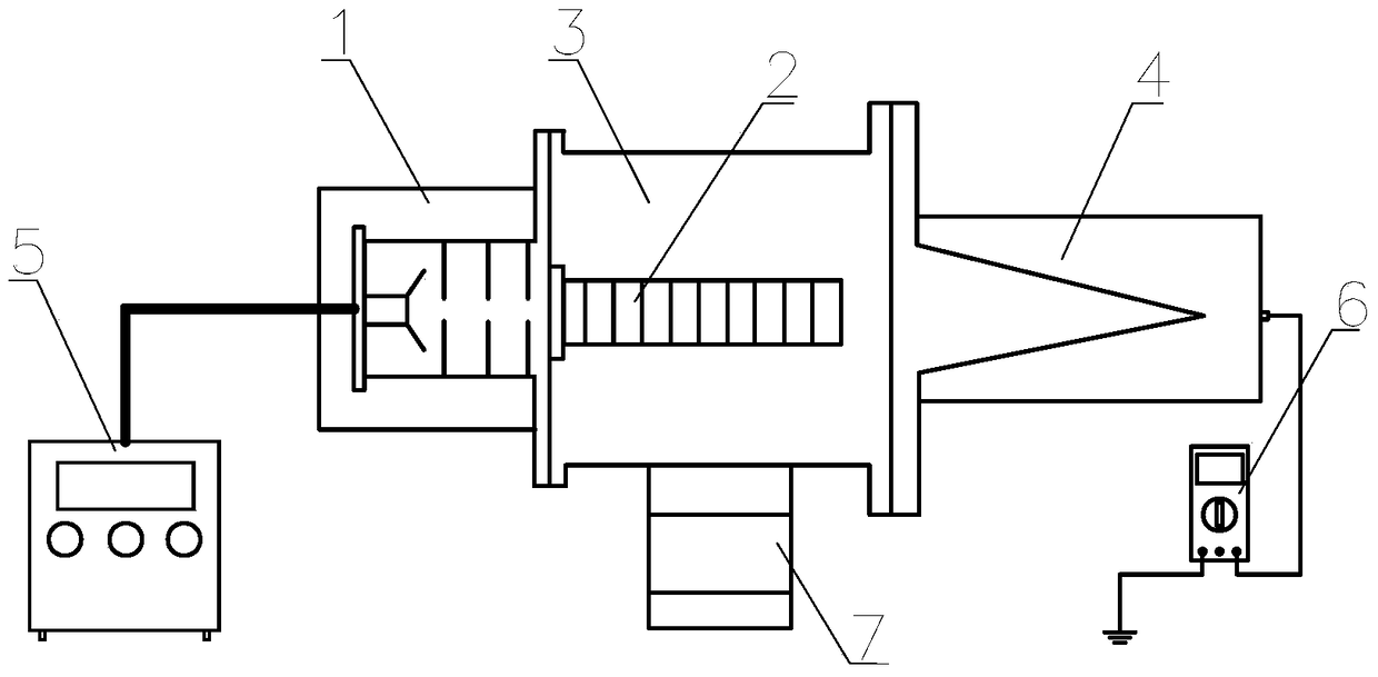
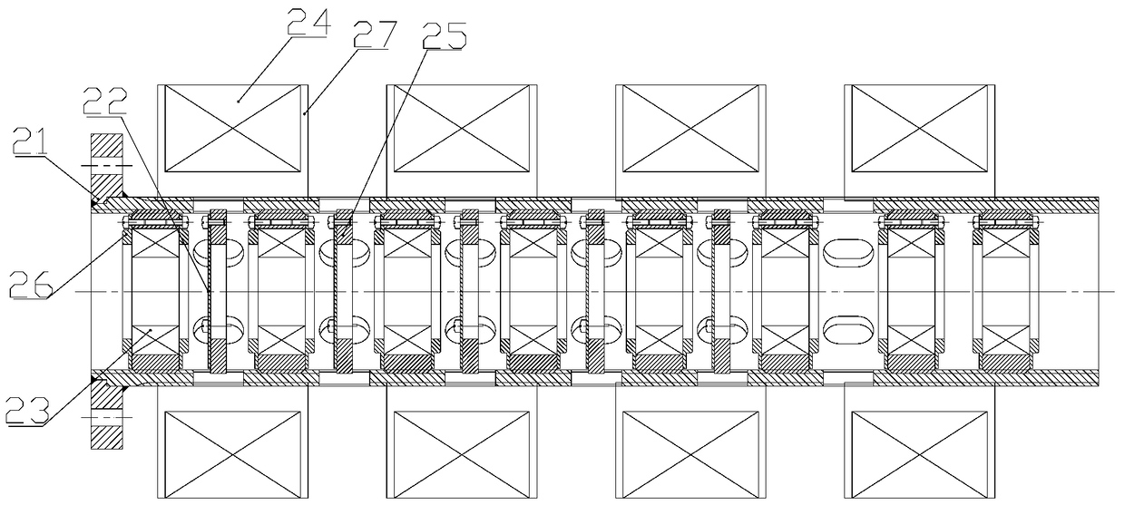
[0034] (1) According to the interface size of electron beam source 1 (flange diameter 100mm), estimated diameter of electron beam (10mm), size of permanent magnet lens 23 (outer diameter 40mm, inner diameter 30mm, axial length 15mm) and transport extraction distance (400mm) design measurement axis 21, metal film 22, metal film support 25 and permanent magnet lens support 26: measurement axis 21 mounting flange diameter is 100mm, inner surface is M52×2mm internal thread, outer surface diameter is 64mm, length is 400mm; the metal film 22 is a titanium film with an outer diameter of 40 mm and a thickness of 0.1 mm; the inner diameter of the metal film support 25 is 30 mm, the outer surface is an M52×2 mm external thread, and the thickness is 5 mm; the inner diameter of the permanent magnet lens support 26 is 30 mm. The surface is M52×2mm external thread, and the thickness is 18mm.
[0035] (2) According to the arrangement of the permanent magnet lenses 23 to be measured (place 4 ...
Embodiment 2
[0040] (1) According to the electron beam source 1 interface size (flange diameter 150mm), estimated electron beam diameter (6mm), electromagnetic lens 24 size (outer diameter 180mm, inner diameter 80mm, axial length 60mm) and transport extraction distance ( 390mm) design measurement shaft 21, metal film 22, metal film support 25 and electromagnetic lens support 27: the diameter of the measuring shaft 21 mounting flange is 150mm, the inner surface is M45×2mm internal thread, and the outer surface is M60×2.5mm external thread , the length is 390mm; the metal film 22 is a titanium film with an outer diameter of 38mm and a thickness of 0.1mm; the inner diameter of the metal film support 25 is 32mm, the outer surface is an M45×2mm external thread, and the thickness is 5mm; the inner surface of the electromagnetic lens support 27 is M60×2.5mm internal thread, outer diameter 80mm, thickness 40mm, lens baffles with 2mm outer diameter and 180mm outer diameter at both ends.
[0041](2)...
PUM
 Abstract
Description
Claims
Application Information
 - R&D Engineer
- R&D Manager
- IP Professional
- Industry Leading Data Capabilities
- Powerful AI technology
- Patent DNA Extraction
Browse by: Latest US Patents, China's latest patents, Technical Efficacy Thesaurus, Application Domain, Technology Topic, Popular Technical Reports.
© 2024 PatSnap. All rights reserved.Legal|Privacy policy|Modern Slavery Act Transparency Statement|Sitemap|About US| Contact US: help@patsnap.com