Motor wire-outgoing clamp

A cable outlet clip and wire clamping technology, applied in the direction of electrical components, electromechanical devices, electric components, etc., can solve the problems of troublesome operation, low installation efficiency, and loose closing, etc., and achieve the effect of simple operation and high installation efficiency.

Inactive Publication Date: 2016-04-13
GREE ELECTRIC APPLIANCES INC OF ZHUHAI
View PDF5 Cites 9 Cited by
  • Summary
  • Abstract
  • Description
  • Claims
  • Application Information

AI Technical Summary

Problems solved by technology

The outlet clip structure in the prior art usually adopts a structure with upper and lower sheaths separated, which has some problems in production and use: on the one hand, when the outlet clip with the upper and lower sheaths separated structure clamps the power cord, it needs Separate the upper and lower sheaths first, place the power cord in the wire clamping groove, and then install the upper and lower sheaths together. The upper and lower sheaths are set separately, and you need to find a pair, and you need to manually align the connecting parts of the upper and lower sheaths when snapping them together. , to complete the fastening, and the operation is cumbersome, and the installation efficiency is low; on the other hand, after the power cord is clamped by the outlet clip, the front end of the outlet clip is prone to open, not tightly closed, and the power cord cannot be pressed tightly. As a result, the outlet clip loses the function of protecting the wire

Method used


Image

  • Motor wire-outgoing clamp
  • Motor wire-outgoing clamp
  • Motor wire-outgoing clamp

Examples


Embodiment Construction

[0030] In order to further explain the technical means and effects of the present invention to achieve the intended purpose of the invention, the specific implementation, structure, features and effects of the application according to the present invention will be described in detail below in conjunction with the accompanying drawings and preferred embodiments. . In the following description, different "one embodiment" or "embodiment" do not necessarily refer to the same embodiment. Furthermore, the particular features, structures, or characteristics of one or more embodiments may be combined in any suitable manner.

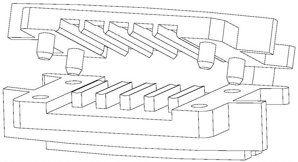
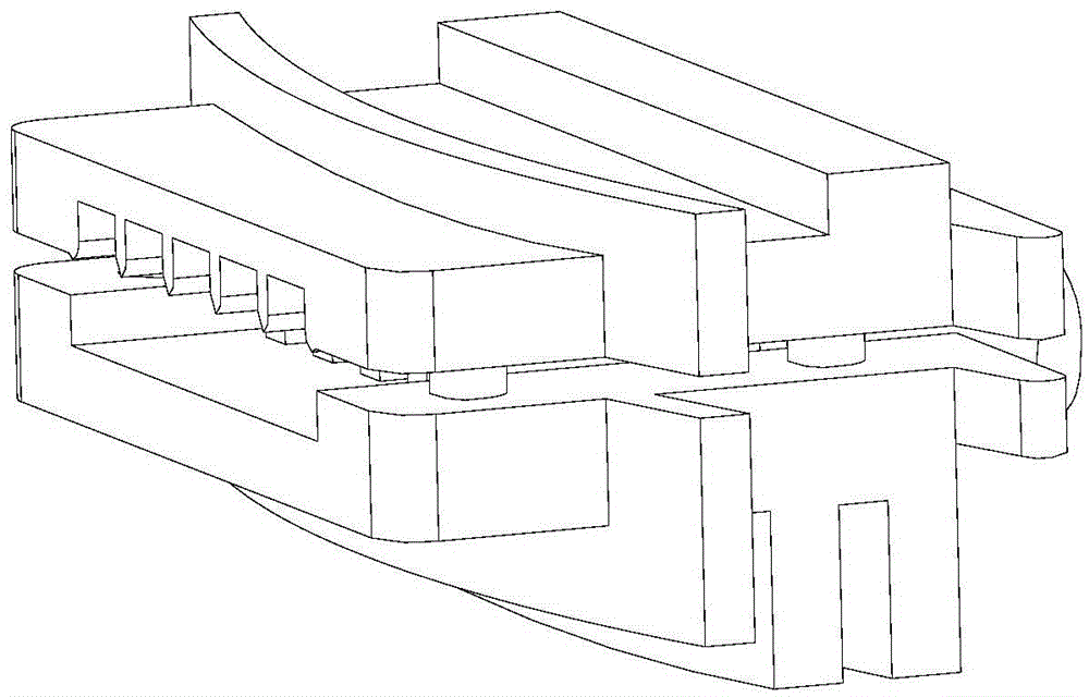
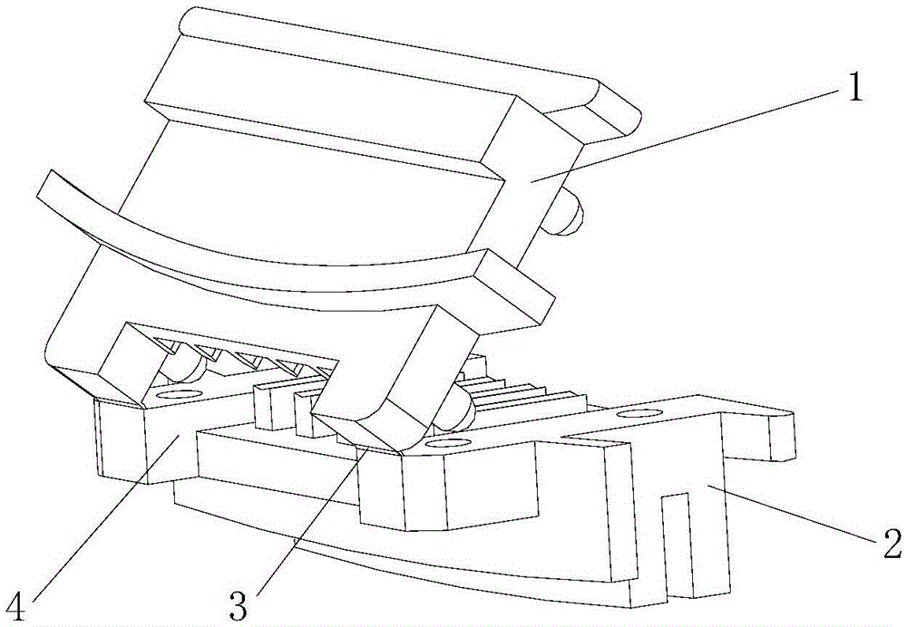
[0031] Such as figure 1 As shown, in order to solve the problems existing in the structure of the upper and lower sheaths with separate outlet clamps, it was conceived to connect the tails of the upper and lower sheaths together through the connecting belt. The outlet clamp is mainly composed of the upper outlet sheath, the lower outlet sheath and the connection...


PUM


Abstract

The invention discloses a motor wire-outgoing clamp, which includes an upper wire-outgoing sheath, a lower wire-outgoing sheath and a connecting mechanism. A wire clamping groove portion and a wire clamping column portion are arranged on the upper wire-outgoing sheath and the lower wire-outgoing sheath respectively. The wire clamping groove portion includes wire clamping grooves extending in a wire penetrating direction. The wire clamping column portion includes wire clamping columns extending in a wire penetrating direction. The wire clamping grooves and the wire clamping columns are cooperated to clamp wires. The two ends of the connecting mechanism are connected to the front end of the upper wire-outgoing sheath and the front end of the lower wire-outgoing sheath, so the upper wire-outgoing sheath and the lower wire-outgoing sheath can be overturned, opened and closed through the connecting mechanism. The motor wire-outgoing clamp is easy to operate. After being turned over, the upper and lower sheaths are fixed in position, and do not need to be aligned again when being folded, so the mounting efficiency is high. Meanwhile, the front end of the motor wire-outgoing clamp is prevented from being closed loosely, and a power line is prevented from being fixed loosely.

Description

technical field [0001] The invention relates to a wire outlet clip, in particular to a motor outlet clip, which belongs to the technical field of motors. Background technique [0002] The outlet clamp is a kind of outlet sheath on the plastic-sealed motor, which plays the role of fixing the power cord and protecting the outlet. It is stuck on the casing of the motor. The plates are separated so as not to fall off at the soldering point. The outlet clip structure in the prior art usually adopts a structure with upper and lower sheaths separated, which has some problems in production and use: on the one hand, when the outlet clip with the upper and lower sheaths separated structure clamps the power cord, it needs Separate the upper and lower sheaths first, place the power cord in the wire clamping groove, and then install the upper and lower sheaths together. The upper and lower sheaths are set separately, and you need to find a pair, and you need to manually align the connec...

Claims


Application Information

Patent Timeline
IPC IPC(8): H02K5/22
CPCH02K5/225H02K2205/00
Inventor 肖胜宇纪泽轩刘丽刚
Owner GREE ELECTRIC APPLIANCES INC OF ZHUHAI
Why Eureka
Try Eureka