Method and device for positioning candidate touch point and touch screen equipment

A touch point and equipment technology, applied in the input/output process of data processing, instruments, electrical digital data processing, etc., can solve the problem of touch point omission

Active Publication Date: 2016-04-13
HISENSE VISUAL TECH CO LTD
View PDF4 Cites 2 Cited by
  • Summary
  • Abstract
  • Description
  • Claims
  • Application Information

AI Technical Summary

Problems solved by technology

[0007] Embodiments of the present invention provide a method, device, and touch screen device for locating candidate touch points, which are used to solve the problem of missing touch points when scanning touch points in the prior art, and can reduce the possibility of missing touch points , thereby improving the positioning accuracy of the touch point

Method used


Image

  • Method and device for positioning candidate touch point and touch screen equipment
  • Method and device for positioning candidate touch point and touch screen equipment
  • Method and device for positioning candidate touch point and touch screen equipment

Examples


Embodiment 1

[0060] Embodiments of the present invention provide a method for locating candidate touch points, which is applied to touch screen devices, such as Figure 5 As shown, the method for positioning candidate touch points includes:

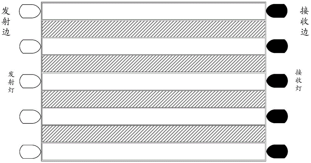
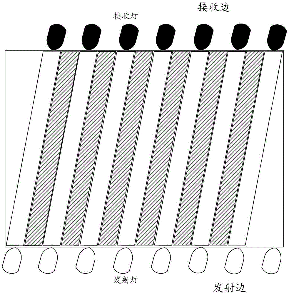
[0061] S101. The device for locating candidate touch points acquires the optical path voltage values ​​on each optical path in the first scanning direction and the optical path voltage values ​​on each optical path in the second scanning direction within one scanning period.

[0062] Wherein, the optical path voltage value on each optical path in the first scanning direction corresponds to the voltage value corresponding to the optical signal received by the receiving lamp corresponding to each optical path in the first scanning direction. The optical path voltage value on each optical path in the second scanning direction corresponds to the voltage value corresponding to the optical signal received by the receiving lamp corresponding to each optical ...

Embodiment 2

[0151] An embodiment of the present invention provides a device for locating candidate touch points, which is included in a touch screen device, such as Figure 25 As shown, the device for locating candidate touch points includes: an acquisition module 21 , an assignment module 22 , a determination module 23 and a calculation module 24 .

[0152] The acquiring module 21 is configured to acquire the optical path voltage values ​​on each optical path in the first scanning direction and the optical path voltage values ​​on each optical path in the second scanning direction within one scanning period, and the optical path voltage values ​​on each optical path are set by The voltage values ​​corresponding to the optical signals received by the receiving lamps corresponding to the above-mentioned respective optical paths.

[0153] An assignment module 22, assigning the optical path voltage values ​​of each blind scanning area in the first scanning direction and the optical path volt...


PUM


Abstract

The embodiments of the invention disclose a method and a device for positioning a candidate touch point and touch screen equipment, relate to the field of touch technology and can improve the positioning precision of a touch point. According to the specific solution, the method comprises: acquiring a light path voltage value on each light path in a first scanning direction and a second scanning direction within a scanning period; assigning the light path voltage value of each scanning blind area in the first scanning direction and the second scanning direction; determining a touch area in the first scanning direction according to the light path voltage value on each light path in the first scanning direction and the light path voltage value of each scanning blind area in the first scanning direction, and determining a touch area in the second scanning direction according to the light path voltage value on each light path in the second scanning direction and the light path voltage value of each scanning blind area in the second scanning direction; and calculating the intersection of the touch area in the first scanning direction and the touch area in the second scanning direction to obtain a candidate touch point. The embodiments of the invention are applied to a process of positioning a touch point.

Description

technical field [0001] The present invention relates to the field of touch technology, in particular to a method, device and touch screen device for locating candidate touch points. Background technique [0002] With the introduction of the new human-computer interaction technology—touch screen technology, the input control mode of electronic products has gradually changed from the traditional keyboard or mouse control mode to the touch screen control mode. Compared with traditional input control methods, touch screen technology can provide users with more simplified human-computer interaction services. [0003] Among them, the infrared touch technology is a common touch screen technology. The infrared touch screen frame adopted by the infrared touch technology has a rectangular structure, and the infrared touch screen frame is composed of a long emitting side, a long receiving side, a short emitting side and a short receiving side. [0004] In the prior art, for the situa...

Claims


Application Information

Patent Timeline
Patent Type & Authority Applications(China)
IPC IPC(8): G06F3/041
CPCG06F3/0418
Inventor 王武军薛晓光
Owner HISENSE VISUAL TECH CO LTD
Why Eureka
Try Eureka