Revolving stage with elastic armrests
A kind of armrest and elastic technology, applied in the field of rotating stage, can solve the problem of not meeting the performance needs, not designing armrests, etc., and achieve the effect of good vibration isolation, good comfort and reliable installation.
- Summary
- Abstract
- Description
- Claims
- Application Information
AI Technical Summary
Problems solved by technology
Method used
Image
Examples
Embodiment 2
[0042] Embodiment two, the difference with embodiment one is:
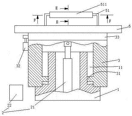
[0043] see Figure 4 , The table top 5 is provided with 3 installation frames 9 . The platform 5 is connected to the slewing bearing 33 through the mounting feet 9 .
[0044] Specifically: the mounting foot 9 includes a lower section 91 and an upper section 92 . The lower end of the lower section 91 is connected with the slewing bearing 5 . The upper end of the lower section 91 is slidably sleeved on the lower end of the upper section 92 . The lower section 81 is provided with a damping spring 93 supporting the upper section 92 . The upper end of the upper section 92 is provided with a connecting ring 921 . An inner ring 922 passes through the connecting ring 921 . The inner ring 922 is connected with the connecting ring 921 through the rubber ring 7 . The inner ring 922 is pierced with connecting pins 923 . The connecting pin 923 is connected with the lower end of the platform 1 .
[0045] see Figure 5...
Embodiment 3
[0050] Embodiment three, the difference with embodiment two is:
[0051] see Figure 9 , The mounting foot 9 is also provided with a driving mechanism 6 . The inner ring 922 is rotatably connected to the rubber ring 7 , and the rubber ring 7 is fixedly connected with the connecting ring 921 .
[0052] The drive mechanism 6 includes a ratchet 61 , a pawl 62 for driving the ratchet, and a drive lever 63 . The ratchet 61 is coaxially connected with the inner ring 922 . The ratchet 61 is integrated with the inner ring 922 . The pawl 62 is fixedly connected to one end of the driving rod 63 . The upper section 92 is provided with a sliding hole 924 . The other end of the driving rod 63 can slide through the sliding hole 924 two-dimensionally. The lower end of the drive rod 63 is slidably hooked to the lower section 91 along the radial direction of the connecting ring 921 (see Figure 4 ) and connected with the next paragraph. The driving rod 63 is provided with a storage hol...
Embodiment 4
[0054] Embodiment four, the difference with embodiment three is:
[0055] see Figure 10 , The lower end of the hollow fixed column 1 is provided with a buried rod installation hole 95 . The lower end of the buried rod installation hole 95 is provided with an inner flange 951 . The mounting holes of the buried poles are threaded holes. A buried rod 94 is threaded through the buried rod mounting hole 95 so that it can be pulled up upwards. The upper end of the buried rod 94 is provided with a protruding ring 941 . The protrusion ring 941 cooperates with the inner flange 951 to prevent the buried rod 94 from falling off downward. An extruded pipe 96 is threadedly connected to the buried rod installation hole 95 . The lower end of the buried rod 94 is provided with a gripping structure 4 . The gripping structure 4 includes a pressing rod 41 , a limiting member 45 and two oppositely arranged curved arms 42 . The pressing rod 41 extends in the vertical direction. The pressi...
PUM
 Abstract
Description
Claims
Application Information
 - R&D
- Intellectual Property
- Life Sciences
- Materials
- Tech Scout
- Unparalleled Data Quality
- Higher Quality Content
- 60% Fewer Hallucinations
Browse by: Latest US Patents, China's latest patents, Technical Efficacy Thesaurus, Application Domain, Technology Topic, Popular Technical Reports.
© 2025 PatSnap. All rights reserved.Legal|Privacy policy|Modern Slavery Act Transparency Statement|Sitemap|About US| Contact US: help@patsnap.com


