
Automatic deviation correction method and system for optical axis of machine core of camera

An automatic deviation correction and camera technology, applied in image communication, television, electrical components, etc., can solve problems such as error-prone, time-consuming, and inaccurate mathematical functions

Active Publication Date: 2016-03-23
GOSUNCN TECH GRP
View PDF4 Cites 12 Cited by
  • Summary
  • Abstract
  • Description
  • Claims
  • Application Information

AI Technical Summary

Problems solved by technology

However, since each camera produced is different, it is necessary to calibrate the optical axis of each camera before measurement, and then manually measure the data for each camera, and then input the data into the camera. bring a lot of work
Moreover, if the measured data is too much, it will be time-consuming and error-prone, and if the measured data is small, the fitted mathematical function will not be accurate enough, and the calculated optical axis deviation will be inaccurate

Method used


Image

  • Automatic deviation correction method and system for optical axis of machine core of camera
  • Automatic deviation correction method and system for optical axis of machine core of camera
  • Automatic deviation correction method and system for optical axis of machine core of camera

Examples


Embodiment

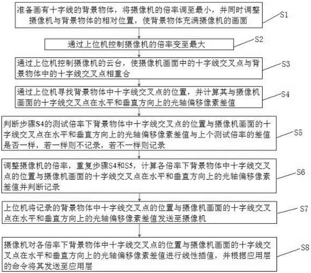
[0051] Example: such as figure 1 As shown, a method for automatically correcting the optical axis of a camera movement includes:

[0052] S1. Prepare the background object with crosshairs, adjust the magnification of the camera to the minimum, and adjust the relative position between the camera and the background object at the same time, so that the background object fills the image of the camera;

[0053] S2. Change the magnification of the camera to the maximum through the host computer;

[0054] S3. Control the pan / tilt of the camera through the host computer, so that the intersection point of the crosshairs in the camera picture coincides with the intersection point of the crosshairs in the background object;

[0055] S4. Find the position of the intersection point of the crosshairs in the background object through the host computer, and calculate the optical axis offset pixel difference between the intersection point of the crosshairs and the camera screen in the horizon...


PUM


Abstract

The invention discloses an automatic deviation correction method for an optical axis of a machine core of a camera. The automatic deviation correction method comprises the steps of preparing a background object on which cross curves are drawn, adjusting the multiplying power of the camera to the minimum and adjusting relative positions of the camera and the background object to enable the background object to be fill with the frame of the camera; controlling the multiplying power of the camera to the maximum; enabling the intersection of the cross curves in the camera frame to be overlapped with the intersection of the cross curves in the background object; finding the position of the intersection of the cross curves in the background object and calculating an optical axis deviation pixel difference value between the position of the intersection of the cross curves in the background object and the intersection of the cross curves of the camera frame in horizontal and vertical directions and in the presence of each multiplying power; judging whether the optical axis deviation pixel difference value between the position of the intersection of the cross curves in the background object and the intersection of the cross curves of the camera frame in the horizontal and vertical directions and in the presence of one test multiplying power is as same as the difference value in the presence of the last test multiplying power; if not, recording; and sending the recorded optical axis deviation pixel difference value to the camera. The automatic deviation correction method and system for the optical axis of the machine core of the camera are automatic and simple; and cost is saved.

Description

technical field [0001] The invention relates to the field of video security monitoring, in particular to a method and system for automatically correcting the optical axis of a camera core. Background technique [0002] The general camera movement has the function of zooming, that is, the function of zooming in and out on the object being photographed. When the zoom of the camera movement changes, the optical axis will shift. In layman's terms, the optical axis shift is when an object is seen at the center of the screen at a certain magnification, but after zooming in or out, the object is usually not still at the center, but toward the center of the screen. Up, down, left or right shifted, this shift is the optical axis shift. Optical axis offset can cause large errors in the camera system and needs to be corrected. To correct the optical axis offset, the optical axis offset must be measured first. To correct the optical axis offset, the magnitude of the optical axis offs...

Claims


Application Information

Patent Timeline
IPC IPC(8): H04N17/00
CPCH04N17/002
Inventor 李江明胡颖俞翔张永涛吴均寿汪刚刘双广
Owner GOSUNCN TECH GRP
Learn More