Casting Method of Steam Turbine Valve Housing Castings

A technology for steam turbines and valve casings, which is applied to casting molding equipment, casting molds, and casting mold components, and can solve problems such as easy cutting of castings, difficulty in setting up hidden risers, and difficulty in ensuring the size of castings

Active Publication Date: 2017-10-31
KOCEL STEEL
View PDF5 Cites 0 Cited by
  • Summary
  • Abstract
  • Description
  • Claims
  • Application Information

AI Technical Summary

Problems solved by technology

[0003] The above-mentioned casting method has the following problems: 1. Because a hidden riser is arranged in the inner cavity of the casting, it is easy to cause sand sticking in the inner cavity of the casting, and it is easy to cut the casting when cutting, and it is difficult to set the dark riser, which is not conducive to casting feeding; 2. There is no core head at the hidden riser of the 1# sand core in the inner cavity, which makes it difficult to locate the sand core and ensure the size of the casting; 3. The molding of this casting method is divided into upper, middle and lower boxes, and the actual production efficiency is low. The labor intensity of the operator is high

Method used


Image

  • Casting Method of Steam Turbine Valve Housing Castings
  • Casting Method of Steam Turbine Valve Housing Castings
  • Casting Method of Steam Turbine Valve Housing Castings

Examples


Embodiment Construction

[0019] The invention provides a casting method of steam turbine valve housing castings, please refer to Figure 4 to Figure 7 , including the following steps:

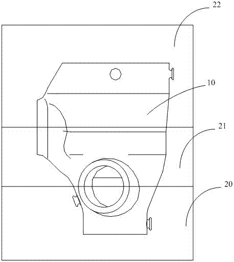
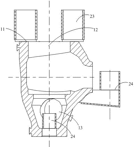
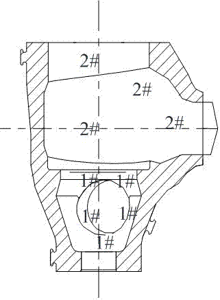
[0020] Step S300, separate manufacturing of the solid model of the steam turbine valve casing casting: select the largest section of the steam turbine valve casing casting as the parting surface, and make the corresponding upper valve casing casting solid model split 31 and the lower valve casing casting solid model split 32. After the split 31 of the solid model of the upper valve casing is matched with the split 32 of the solid model of the lower valve casing, a solid model of the solid model of the steam turbine valve casing corresponding to the casting of the steam turbine valve casing is formed, and the middle nozzle 33 is located on the upper valve casing On the split body 31 of the casting solid model, the middle nozzle 33 is parallel to the parting surface.

[0021] Step S301, modeling: lower box molding, plac...


PUM

PropertyMeasurementUnit
diameteraaaaaaaaaa
diameteraaaaaaaaaa

Abstract

A novel casting method for a steam turbine valve shell casting comprises the following steps that solid model split parts of the steam turbine valve shell casting are manufactured, the maximum section of the steam turbine valve shell casting is selected as a parting surface, the corresponding upper valve shell casting solid model split part and the corresponding lower valve shell casting solid model split part are manufactured, and a middle pipe opening is located in the upper valve shell casting solid model split part; modeling is carried out, lower box modeling is carried out, a sand box and the lower valve shell casting solid model split part are arranged on a modeling platform, quick sand modeling is carried out, a pouring system is laid, and box overturning is carried out after placement is conducted for preset time; upper box modeling is carried out, the other sand box and the upper valve shell casting solid model split part are arranged on a lower box, quick sand modeling is carried out, and open risers are arranged on the side walls, close to the middle pipe opening, of the upper valve shell casting solid model split part and the end pipe opening, far away from the flange face, of the upper valve shell casting solid model split part; a sand core of an inner cavity of the steam turbine valve shell casting is manufactured; and after core setting, box combining, pouring, cooling and box beating, the steam turbine valve shell casting is finally obtained.

Description

technical field [0001] The invention relates to the technical field of casting, in particular to a casting method of a steam turbine valve housing casting. Background technique [0002] The casting structure of steam turbine valve casing is complex, with many nozzles and different angles, so it is difficult to shape. At the same time, the inner cavity space of the casting is narrow, and the space for setting the riser is small, which makes it difficult to feed the casting. In the prior art, the casting process of such castings is as Figure 1 to Figure 3 As shown, the flange surface 11 of the steam turbine valve casing casting solid model 10 corresponding to the steam turbine valve casing casting is horizontally upward, and is divided into a lower box 20, a middle box 21, and an upper box 22 for molding; An open riser 23 is set on the surface 11, and a dark riser 24 is set on the end of the solid model 10 of the steam turbine valve casing casting near the middle nozzle 12 a...

Claims


Application Information

Patent Timeline
Patent Type & Authority Patents(China)
IPC IPC(8): B22C9/24
CPCB22C9/24
Inventor 张立文徐鹏波张学君
Owner KOCEL STEEL
Why Eureka
Try Eureka