
Small focus-fixed solar cooker

A fixed focus, solar cooker technology, applied in the field of solar cookers, can solve the problems of high cost, caustics, perfect accuracy, etc., and achieve the effects of cost reduction, convenient use and simple structure

Inactive Publication Date: 2016-02-24
侯阳
View PDF0 Cites 4 Cited by
  • Summary
  • Abstract
  • Description
  • Claims
  • Application Information

AI Technical Summary

Problems solved by technology

[0003] Most of the current solar cookers do not have a fixed focus when tracking sunlight. Therefore, people hope to have a solar cooker with a fixed focus and a simple structure, and various schemes have been proposed. For example, some solar cookers use elastic materials to make reflectors. The focus is fixed by the curvature of the mirror, but it is proved that the curvature adjustment of the mirror is difficult to be perfect and accurate as in theory. Some people fix the focus by replacing the mirror with different curvature. Changing the reflector will cause caustics, which is inconvenient to use

Method used


Image

  • Small focus-fixed solar cooker
  • Small focus-fixed solar cooker
  • Small focus-fixed solar cooker

Examples


Embodiment approach 1

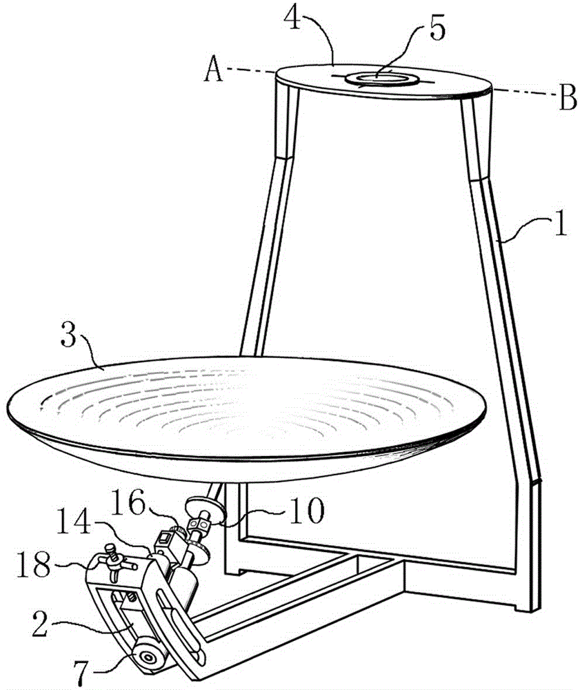
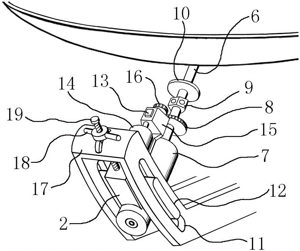
[0022] Implementation mode 1: if figure 1 , figure 2 , is an embodiment in which the slide track is used to track the sun elevation angle (altitude angle). The upper end of the base (1) is provided with a stove (4), and the stove (5) is horizontally arranged on the stove (4); the base (1) There are left-right symmetrical arc-shaped slideways (11) on both sides of the front end below, and the virtual axis (AB) of the slideway (11) is horizontally arranged at the center of the bottom plane of the cooking range (5), and the movable seat (2) both sides There is a sliding sleeve (12), the base (1) is connected to the sliding sleeve (12) of the movable seat (2) through the slideway (11), and the central angle of the slideway (11) is greater than the annual elevation angle of the sun and the sliding sleeve (12) The sum of the corresponding central angles; there is a main shaft sleeve (7) on the movable seat (2), and a bearing is arranged in the main shaft sleeve (7), and the main s...

Embodiment approach 2

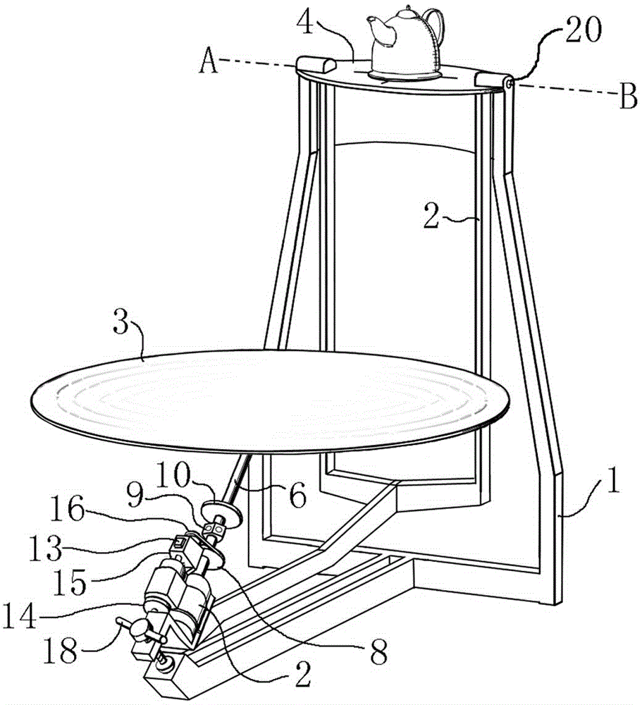
[0025] Implementation mode 2: if image 3 , is an embodiment in which the support shaft (20) is used to track the elevation angle of the sun, a pair of short support shafts (20) are horizontally arranged on both sides of the upper end of the base (1), and the stove (5) is horizontally arranged in the middle of the support shaft (20) On the stove (4), the axis line (AB) of the support shaft (20) coincides with the center of the bottom plane of the stove (5), and the movable seat (2) is socketed with the support shaft (20) through the round holes on both sides; There is a main shaft sleeve (7) on the movable seat (2), the main shaft (6) is arranged in the main shaft sleeve (7), and the axis line (AB) of the extension line of the main shaft (6) and the support shaft (20) is in the range ( The center of the bottom plane of 5) intersects vertically; the Fresnel concentrating mirror (3) is obliquely fixed on the front end of the main shaft (6), and the main optical axis of the mirro...

Embodiment approach 3

[0027] Embodiment 3: The structure is the same as Embodiment 1 or 2, the difference is that the stove (5) is separated from the base (1) and is installed indoors independently, the base (1) is installed on the south side of the outdoor, and the middle wall is provided with light hole.


PUM


Abstract

The invention relates to a small focus-fixed solar cooker. According to the small focus-fixed solar cooker, a rotary movable seat is arranged on a base and provided with a main shaft sleeve; a main shaft is arranged in the main shaft sleeve through a bearing; a reflection mirror is fixed to the end of the main shaft; a cooker body is arranged on the extending line of the main shaft. The small focus-fixed solar cooker is convenient to use and simple in structure, automatic tracking of the azimuth angle and manual adjustment of the elevation angle are combined, the focus is fixed to the cooker body on the crosspoint of the virtual axis (or a supporting shaft) of a slideway and the extending line of the main shaft, focusing is accurate, and the arrangement of the cooker body meets the requirements of ergonomics.

Description

technical field [0001] The invention relates to a solar cooker, especially a small fixed-focus solar cooker. Background technique [0002] The solar cooker gathers the solar radiation energy to one point, and is used for cooking, cooking, etc. The use of the solar cooker is clean and pollution-free, suitable for local utilization, and the solar energy is inexhaustible. [0003] Most of the current solar cookers do not have a fixed focus when tracking sunlight. Therefore, people hope to have a solar cooker with a fixed focus and a simple structure, and various schemes have been proposed. For example, some solar cookers use elastic materials to make reflectors. The focus is fixed by the curvature of the mirror, but it is proved that the curvature adjustment of the mirror is difficult to be perfect and accurate as in theory. Some people fix the focus by replacing the mirror with different curvature. Changing the reflector will cause caustics, which is also inconvenient to use....

Claims


Application Information

Patent Timeline
IPC IPC(8): F24J2/02F24S20/30
CPCF24S20/30F24S23/71F24S30/40F24S50/20Y02B40/18Y02E10/47
Inventor 侯阳
Owner 侯阳
Learn More