
Electronic component storage box

An electronic component and storage room technology, applied in the field of storage boxes, can solve the problems of low efficiency, restricted production capacity, artificial wasteful consumption, etc., and achieves the effects of large storage quantity, simple structure and high storage efficiency

Inactive Publication Date: 2016-02-03
SUZHOU YUANSHUO PRECISION MOLD
View PDF8 Cites 0 Cited by
  • Summary
  • Abstract
  • Description
  • Claims
  • Application Information

AI Technical Summary

Problems solved by technology

Therefore, in the process of continuous arranging and breaking up, a lot of labor is wasted in vain, and the efficiency is low, which seriously restricts the production capacity

Method used


Image

  • Electronic component storage box
  • Electronic component storage box
  • Electronic component storage box

Examples


Embodiment 1

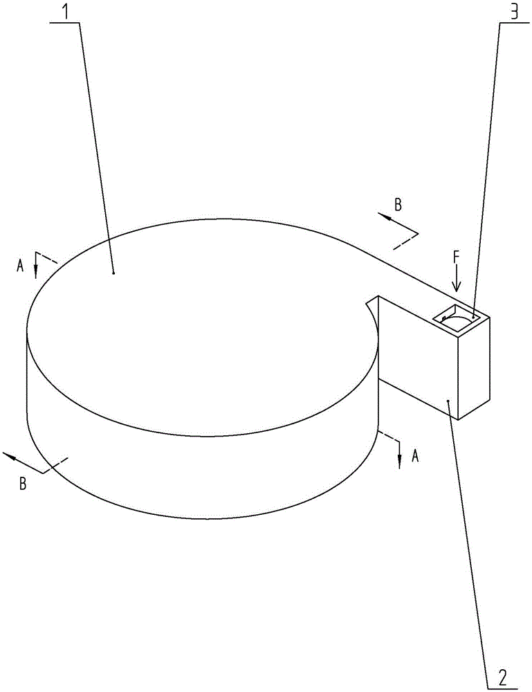
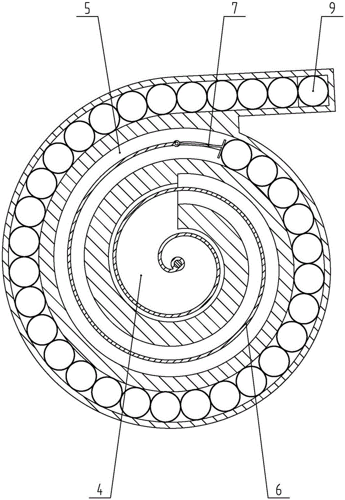
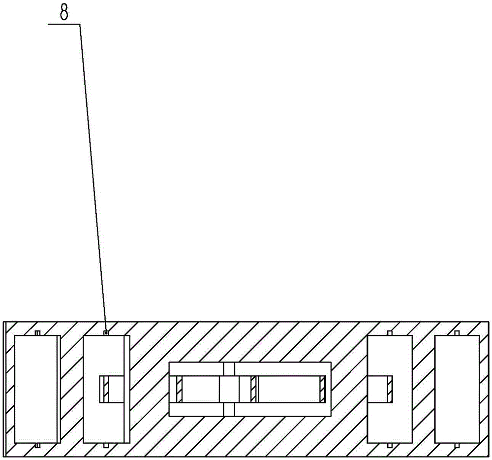
[0017] like Figures 1 to 3 As shown, an electronic component storage box includes a casing 1 formed by injection molding of hard plastic and having a cavity. a convex portion 2 . A front end of the convex part 2 is provided with a cover body (not shown), and the cover body is detachably mounted on the front end of the convex part 2 by bolts. The cavity includes a first storage chamber 4 located in the middle of the housing 1 and a second storage chamber 5 surrounding the first storage chamber 4 and having a spiral structure. The inner end of the second storage chamber 5 communicates with the first storage chamber 4, and its outer end extends into the convex portion 2; the convex portion 2 is provided with a through hole 3 through the side wall, and the outer end of the second storage chamber 5 passes through the through hole 3 communicate with the outside. A clockwork spring 6 is arranged in the cavity, and a movable block 7 is arranged in the second storage chamber 5 ; T...

Embodiment 2

[0019] The difference from Embodiment 1 is that in this embodiment, the cover body is hinged with the convex shell through a pin shaft, and the movable end of the cover body can be locked or released from the convex part 2 through a locking mechanism, so that the cover body can be wound around The pin rotates to close or open the front end of the protrusion 2 .

[0020] When storing the workpieces 9 , the cover at the front end of the convex portion 2 is opened, and the workpieces 9 enter the second storage chamber 5 side by side one by one. As the number of workpieces 9 increases, the movable block 7 gradually squeezes the clockwork spring 6 to make it shrink and has greater potential energy. When the second accommodating chamber has been filled with workpieces 9, it is only necessary to close the cover.

[0021] When taking the piece, a force F aligned with the through hole 3 is applied through the thimble (such as cylinder drive), and the workpiece 9 (the first workpiece) ...


PUM


Abstract

The invention relates to an electronic component storage box which comprises a shell with a chamber, wherein the shell is in a flat cylindrical structure. The electronic component storage box further comprises a convex part formed by extending along tangential direction of the side wall to one side, wherein a cover is arranged at the front end of the convex part. The chamber comprises a first storage chamber positioned in the middle of the shell and a second storage chamber surrounding outside the first storage chamber, and the second storage chamber is provided with a spiral structure. The inner end of the second storage chamber is communicated with the first storage chamber, and the outer end of the second storage chamber extends into the convex part. A through hole penetrating through the side wall is formed in the convex part, and the outer end of the second storage chamber is communicated with the outside through the through hole. A clockwork spring is arranged in the chamber, and a movable block is arranged in the second storage chamber. The inner end of the clockwork spring is fixed at the center of the first storage chamber, and the outer end of the clockwork spring is hinged to the movable block. The electronic component storage box has the beneficial effects that the storage quantity is large, and the storage efficiency is high; in the storage and transport process of electronic components, the electronic component storage box provides additional protection for the electronic components and avoids the electronic components to be damaged due to mutual collision.

Description

technical field [0001] The invention relates to a storage box, in particular to an electronic component storage box used for storing and processing a plurality of tiny electronic components. Background technique [0002] Electronic components are small in size and irregular in shape, so there are many inconveniences in the process of processing and storage. Some electronic components with a cylindrical structure need to be positioned one by one on the station for processing during processing, and then neatly arranged one by one and placed in a special fixture (also known as a magazine) so as to be sent to the next process to continue processing. Therefore, in the process of continuous arranging and breaking up, a large amount of labor is wasted in vain, and the efficiency is low, which seriously restricts the production capacity. How to solve the above problems and design a device that facilitates the orderly storage of workpieces and the transfer between processes is an ur...

Claims


Application Information

Patent Timeline
Patent Type & Authority Applications(China)
IPC IPC(8): B65D85/86B65D25/02
Inventor 何婷朱磊
Owner SUZHOU YUANSHUO PRECISION MOLD
Learn More