
Driving method and driving circuit of TFT substrate and display device thereof

A driving method and driving circuit technology, applied in static indicators, instruments, etc., can solve the problems of insufficient panel charging, inability to meet the polarity mode of the LCD panel, failure of the pre-charging function, etc., and achieve the effect of solving insufficient charging

Inactive Publication Date: 2016-01-20
TCL CHINA STAR OPTOELECTRONICS TECH CO LTD
View PDF6 Cites 6 Cited by
  • Summary
  • Abstract
  • Description
  • Claims
  • Application Information

AI Technical Summary

Problems solved by technology

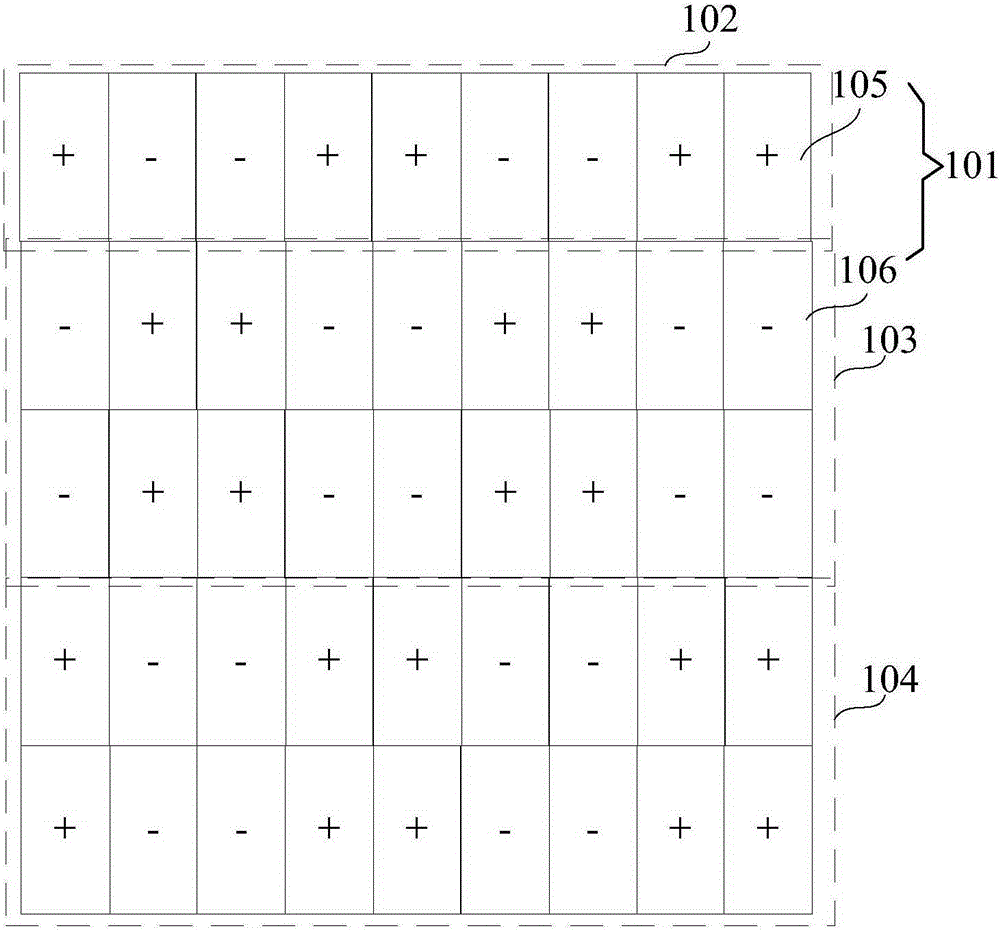
[0003] However, the solutions in the prior art cannot satisfy the situation that the polarity mode of the LCD panel is the pixel unit with different polarities in the same column, such as the situation when the polarity mode is 1+2line (row).
Due to the opposite polarity of adjacent pixel units in the same column, the pre-charging function will fail, and the panel will be under-charged.

Method used


Image

  • Driving method and driving circuit of TFT substrate and display device thereof
  • Driving method and driving circuit of TFT substrate and display device thereof
  • Driving method and driving circuit of TFT substrate and display device thereof

Examples


Embodiment Construction

[0024] Please also refer to Figure 2-4 , figure 2 It is a schematic structural diagram of a TFT substrate provided by an embodiment of the present invention; image 3 It is a flowchart of a method for driving a TFT substrate provided by an embodiment of the present invention; Figure 4 is the waveform diagram of each signal. Wherein, the driving method of this embodiment is based on the case where the polarity mode of the pixel unit of the TFT substrate is 1+nline (line), wherein n is an integer greater than or equal to 1. Specifically, the first row of pixel units is a polar unit, and every n rows of pixel units from the second row of pixel units are another polar unit, and each pixel unit in each polar unit is adjacent to each other. The polarities of the pixel voltages received by the pixel units of the same column in the polarity units are opposite.

[0025] Among them, when n is 2, the TFT substrate structure is as follows image 3 as shown, image 3 The illustrat...


PUM


Abstract

The invention discloses a driving method and driving circuit of a TFT substrate and a display device. The driving method includes the following steps that: scanning voltage is provided for each row of pixel units sequentially, so that each row of pixel units can be pre-charged; and when an N*(2n+1)-th row of pixel units is pre-charged, scanning voltage is provided again for each row of pixel units from the first row of pixel units sequentially, so that each row of pixel units can be switched on, and pixel voltage is provided for the switched-on pixel units, wherein N is an integer greater than or equal to 1. By means of the above technical schemes of the invention, the problem of insufficient charging can be solved.

Description

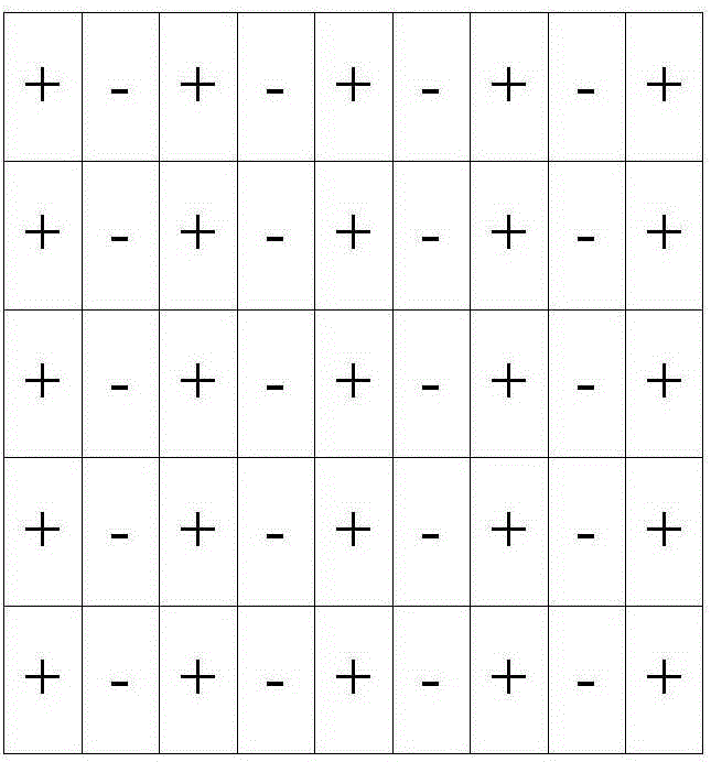
technical field [0001] The invention relates to the field of display technology, in particular to a driving method, a driving circuit and a display device of a TFT substrate. Background technique [0002] Currently, panels with 4K resolution and 2K resolution generally have the problem of insufficient charging time. The scheme that the LCD (LiquidCrystalDisplay, liquid crystal display) panel of prior art adopts is: please refer to figure 1 as shown, figure 1 The polarity switching method of the LCD panel is column inversion (column inversion), that is, the polarity of each column is the same, and the polarity of adjacent columns is opposite. When driving each pixel unit of the LCD panel, the specific method is: provide a scanning voltage to the pixel units of each row in turn, wherein, the time for supplying the scanning voltage to the pixel units of each row is divided into two parts, and in the second half At this time, the pixel unit in the next row of the current row ...

Claims


Application Information

Patent Timeline
Patent Type & Authority Applications(China)
IPC IPC(8): G09G3/36
Inventor 胡安乐吴宇
Owner TCL CHINA STAR OPTOELECTRONICS TECH CO LTD
Learn More