
The Method of Determining the Maximum Design Capacity of High Frequency Transformer

A high-frequency transformer and design capacity technology, which is applied in the field of high-frequency transformers, can solve the problems of small size, meet the volume requirements, improve the power density of the device, and meet the development needs.

Active Publication Date: 2019-03-08
GLOBAL ENERGY INTERCONNECTION RES INST CO LTD +3
View PDF3 Cites 0 Cited by
  • Summary
  • Abstract
  • Description
  • Claims
  • Application Information

AI Technical Summary

Problems solved by technology

[0007] At present, in terms of engineering technology, the design of high-frequency transformers is based on known parameters such as design capacity and frequency. According to the area design formula of high-frequency transformers, the specifications and sizes of the magnetic cores are determined, and then the winding layout is carried out. In the end, this design method can meet the engineering design requirements. However, with the development of power electronic technology, the future power electronic transformer will have larger capacity, smaller volume, and more device integration. , the volume requirements for the high-frequency transformer will be more stringent and precise

Method used


Image

  • The Method of Determining the Maximum Design Capacity of High Frequency Transformer
  • The Method of Determining the Maximum Design Capacity of High Frequency Transformer
  • The Method of Determining the Maximum Design Capacity of High Frequency Transformer

Examples


Embodiment Construction

[0056] Embodiments of the present invention are described in detail below, examples of which are shown in the drawings, wherein the same or similar reference numerals designate the same or similar elements or elements having the same or similar functions throughout. The embodiments described below by referring to the figures are exemplary and are intended to explain the present invention and should not be construed as limiting the present invention.

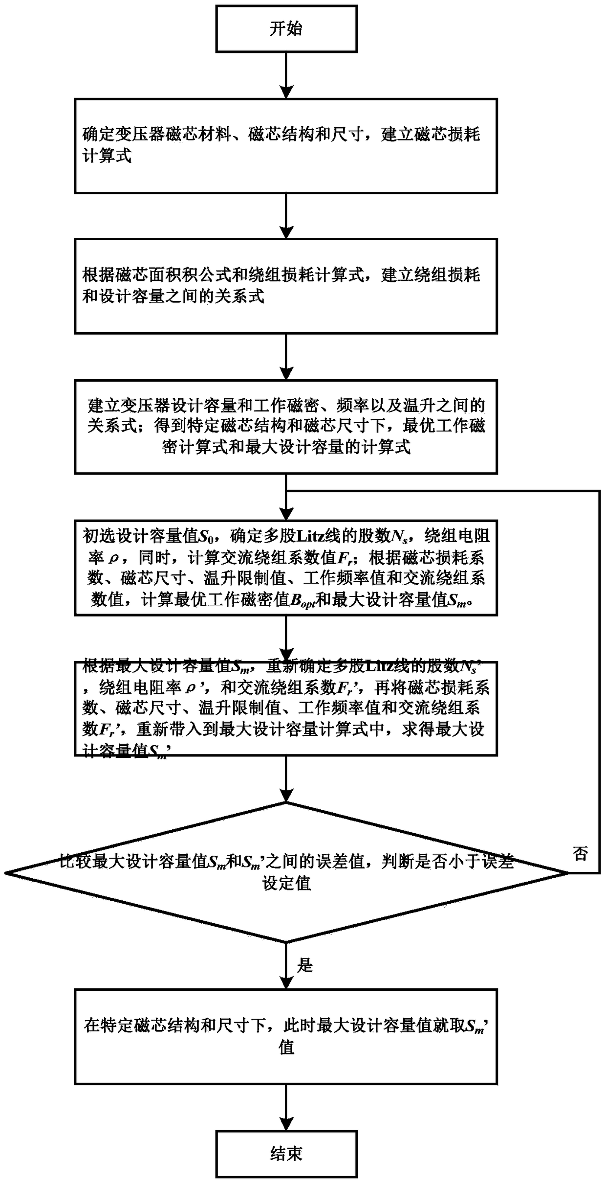
[0057] An embodiment of a method for determining the maximum design capacity of a high-frequency transformer provided by the present invention is as follows: figure 1 As shown, specifically:

[0058] 1. Obtain the core loss coefficient and core loss index of the high-frequency transformer according to the core material of the high-frequency transformer.

[0059] In this embodiment, the transformation ratio of the high-frequency transformer is 1:1, which plays the role of isolation, and isolates the electrical equipment on the se...


PUM


Abstract

The invention provides a determining method for the maximum design capacity of a high-frequency transformer. The determining method includes the steps that 1, the magnetic core loss coefficient of the high-frequency transformer is obtained; 2, the magnetic core area Ap, magnetic core volume Vcore and magnetic core window area Wa of the high-frequency transformer and a temperature increase coefficient Ks are obtained; 3, the optimal working magnetic flux density value Bopt of the high-frequency transformer is calculated; 4, the value of primary design capacity S0, the winding number of a primary winding and a secondary winding of the high-frequency transformer, an alternate-current winding coefficient Fr and the average winding length MLT of the primary winding and the secondary winding are calculated; 5, the maximum design capacity Sm is calculated; 6, new maximum design capacity S'm is calculated; 7, the new maximum design capacity S'm and the maximum design capacity Sm are compared. Compared with the prior art, under the condition that the structure and size of a magnetic core are fixed, the maximum design capacity value of the transformer can be convenient to determine.

Description

technical field [0001] The invention relates to the technical field of high-frequency transformers, in particular to a method for determining the maximum design capacity of a high-frequency transformer. Background technique [0002] Based on power electronics technology, scholars at home and abroad have begun to explore and study a new type of intelligent transformer that realizes electric energy conversion - Power Electronic Transformer (PET for short), also known as Solid-State Transformer (SST for short). As a highly controllable new type of substation equipment, the power electronic transformer is characterized by the ability to flexibly control the voltage amplitude and phase of the primary and secondary sides of the transformer to meet many new requirements for the future development of smart grids. In the realization of the high-power topology of the power electronic transformer, the high-frequency transformer body in the middle is the most basic and most important el...

Claims


Application Information

Patent Timeline
Patent Type & Authority Patents(China)
IPC IPC(8): G06F17/50H01F41/00
Inventor 张宁刘可可王帅兵李琳魏晓光张升高阳周万迪王新颖丁骁
Owner GLOBAL ENERGY INTERCONNECTION RES INST CO LTD
Learn More