
Transition device and transition method of smart card conveying mechanisms

A conveying mechanism and smart card technology, applied to conveyors, conveyor objects, transportation and packaging, etc., can solve problems such as low production efficiency, high labor costs, and poor production continuity, and achieve simple combination and use, reduce labor costs, and improve The effect of production efficiency

Active Publication Date: 2015-12-16
惠州市众宏通智能卡有限公司
View PDF8 Cites 1 Cited by
  • Summary
  • Abstract
  • Description
  • Claims
  • Application Information

AI Technical Summary

Problems solved by technology

When using multiple processing equipment to process cards, the cards need to be transferred between each processing equipment, resulting in poor production continuity, low production efficiency, and manual participation in card transfer is required, resulting in high labor costs
However, if you want to combine two processing equipment to work together, since each processing equipment has an independent card conveying mechanism, the card conveying mechanism between the two processing equipment cannot successfully complete the connection of card conveying, so it is difficult to realize
Especially between two processing equipment with inconsistent conveying frequencies, it is more difficult to realize the docking of the card conveying mechanisms of the two devices

Method used


Image

  • Transition device and transition method of smart card conveying mechanisms
  • Transition device and transition method of smart card conveying mechanisms
  • Transition device and transition method of smart card conveying mechanisms

Examples


Embodiment Construction

[0045] The present invention will be further described in detail below in conjunction with the embodiments and the accompanying drawings, but the embodiments of the present invention are not limited thereto.

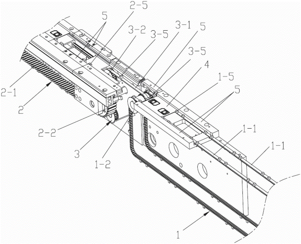
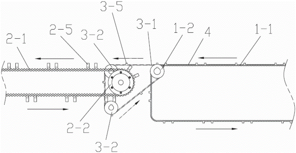
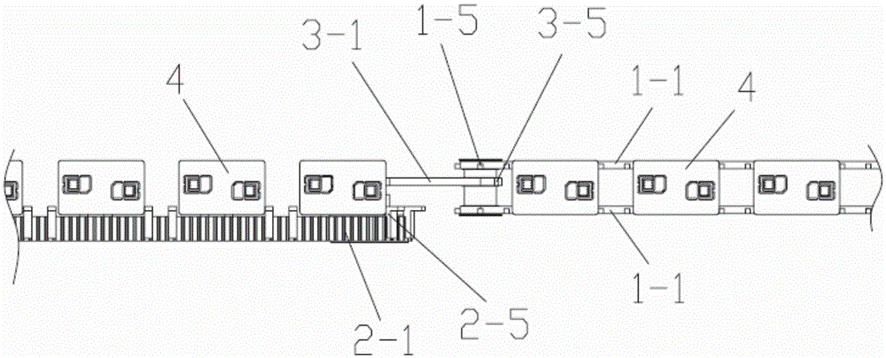
[0046] see Figure 1 ~ Figure 3 , the connecting device of the smart card conveying mechanism of the present invention includes a connecting mechanism 3 arranged between the first card conveying mechanism 1 of the first processing equipment and the second card conveying mechanism 2 of the second processing equipment. in:

[0047] see Figure 1 ~ Figure 4 The first card conveying mechanism 1 includes a first synchronous conveyor belt 1-1 in a closed loop structure and a first driving power mechanism that drives the first synchronous conveyor belt 1-1 to move step by step in a circular manner. There are multiple groups of shifting teeth 1-5 evenly arranged on the synchronous conveyor belt 1-1, and the combination of the shifting teeth 1-5 in each group of shifting teeth ...


PUM


Abstract

The invention discloses a transition device and transition method of smart card conveying mechanisms. The transition device comprises a transition mechanism arranged between the first card conveying mechanism and the second card conveying mechanism. Each of the first card conveying mechanism, the second card conveying mechanism and the transition mechanism comprises a synchronous conveying belt and a power mechanism. A plurality of sets of thumbing teeth are uniformly arranged on each synchronous conveying belt; a first transition conveying position and a second transition conveying position are arranged at the work part of the transition synchronous conveying belt; the last conveying position on the work part of the first synchronous conveying belt coincides with the first transition conveying position; the first conveying position on the work part of the second synchronous conveying belt coincides with the second transition conveying position. According to the invention, two processing devices can be combined in work to achieve coordinated transition, coherent transition of cards can be achieved, the production efficiency can be improved, and the manual cost can be lowered.

Description

technical field [0001] The invention relates to production equipment and methods of smart cards, in particular to a connecting device and a connecting method of a smart card conveying mechanism. Background technique [0002] In the production process of the smart card, the card needs to go through multiple processing steps to obtain the finished product. In the prior art, part of the processing procedures are usually assembled on one processing device, and the complete processing process of the card needs to be processed by multiple processing devices in sequence. When multiple processing equipment is used to process cards, the cards need to be transferred between each processing equipment, resulting in poor production continuity, low production efficiency, and manual participation in card transfer is required, resulting in high labor costs. However, if two processing equipments are to be combined to work together, since each processing equipment has an independent card con...

Claims


Application Information

Patent Timeline
IPC IPC(8): B65G15/12B65G47/52
Inventor 王开来房训军
Owner 惠州市众宏通智能卡有限公司
Learn More