
Flywheel bolt screwing mechanism

A bolt and flywheel technology, which is applied in the field of flywheel bolt tightening mechanism, can solve the problems of incompatibility with powertrain, inability to achieve collinearity, and low efficiency, and achieve the effects of simple mechanism, reduced production cost, and convenient use

Active Publication Date: 2015-12-16
CHERY AUTOMOBILE CO LTD
View PDF4 Cites 2 Cited by
  • Summary
  • Abstract
  • Description
  • Claims
  • Application Information

AI Technical Summary

Problems solved by technology

The existing flywheel bolt tightening equipment is relatively inefficient, and cannot be compatible with these two powertrains, and cannot achieve collinearity. If the equipment is purchased separately, the cost will be high and the cycle will be long

Method used


Image

  • Flywheel bolt screwing mechanism
  • Flywheel bolt screwing mechanism
  • Flywheel bolt screwing mechanism

Examples


Embodiment Construction

[0018] The specific implementation manner of the present invention will be described in further detail below by describing the embodiments with reference to the accompanying drawings.

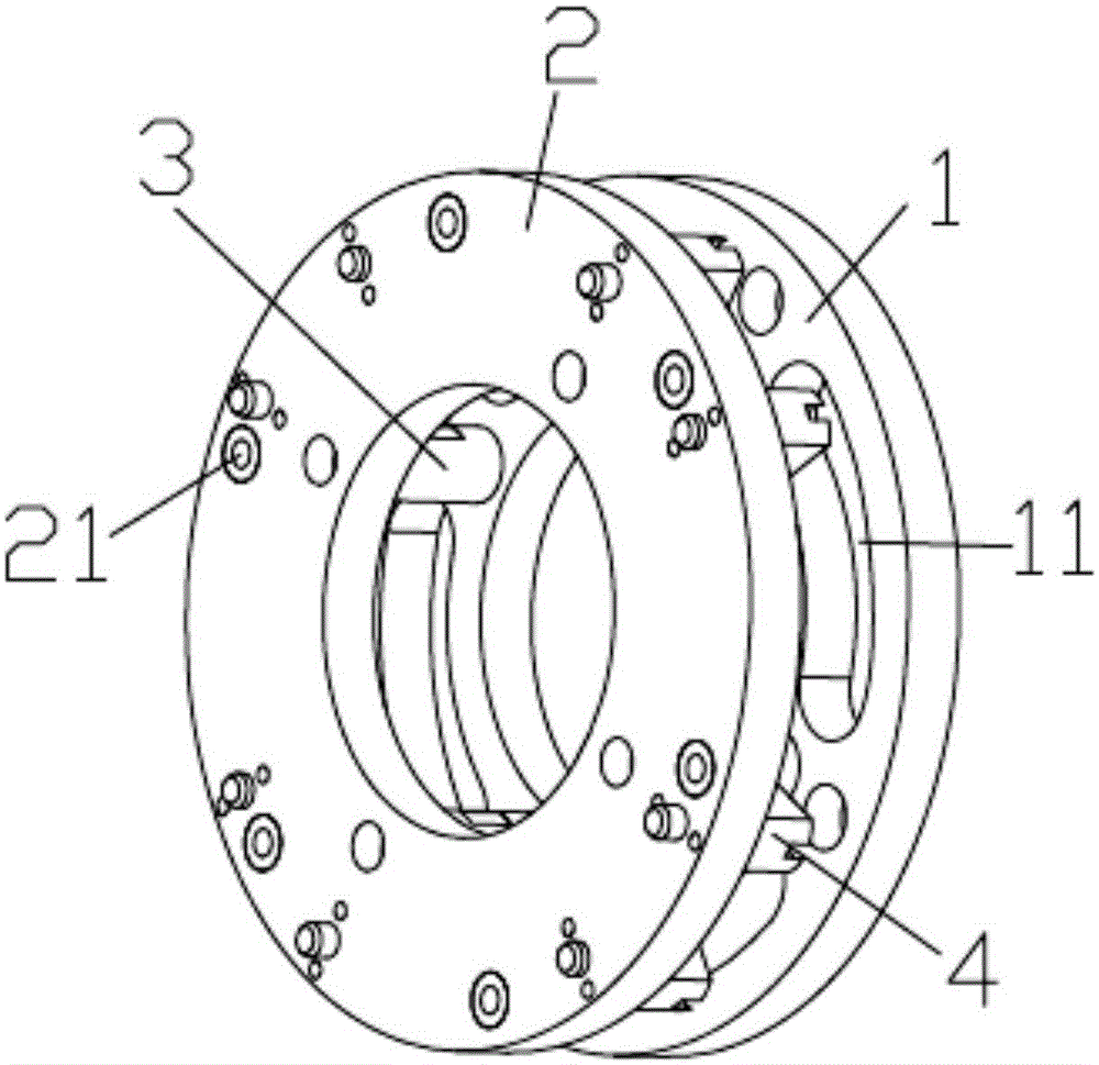
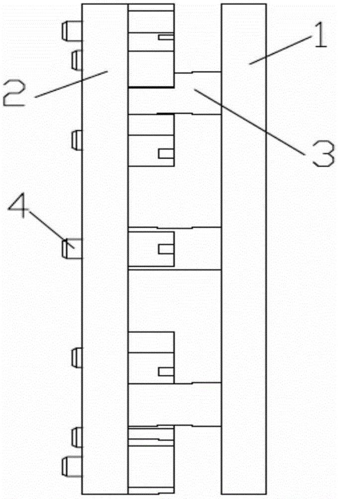
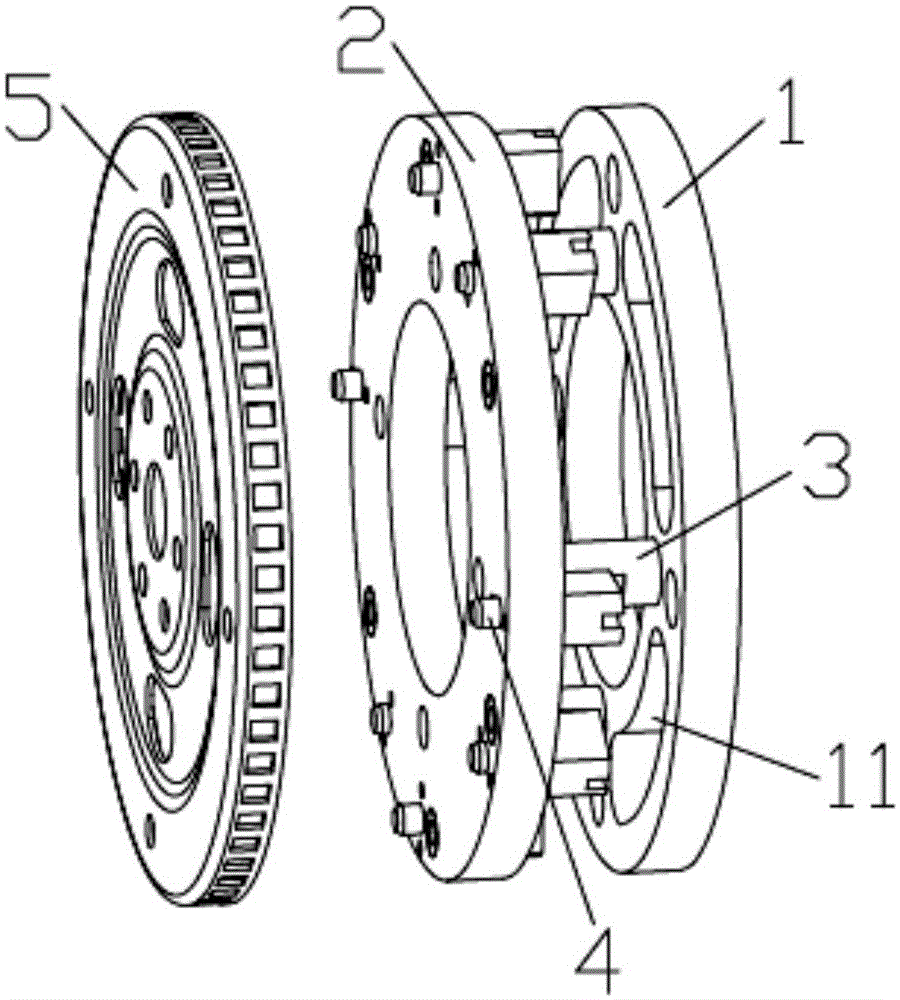
[0019] The flywheel bolt tightening mechanism of the present invention includes a bolt twisting rod, and a driving motor drives the bolt twisting rod to rotate, and also includes a positioning mechanism for positioning the flywheel. Such as figure 1 , 2 As shown, the locating mechanism is provided with a locating pin hole 21 cooperating with the pin on the flywheel 6 of the manual transmission engine and an elastic locating pin 4 cooperating with the locating hole on the flexible disk 5 of the automatic transmission engine, and the elastic locating pin 4 in the elastic locating pin 4 The positioning pin is limited by a spring, and the pin head end can elastically shrink into the pin seat. The combined positioning mechanism is applicable to the tightening of flywheels on automatic and manual t...


PUM


Abstract

The invention discloses a flywheel bolt screwing mechanism. The flywheel bolt screwing mechanism comprises a bolt screwing rod. A drive motor drives the bolt screwing rod to rotate. The flywheel bolt screwing mechanism further comprises a positioning mechanism positioning a flywheel. The positioning mechanism is provided with positioning pin holes (21) matched with pins on the flywheel (6) on a manual gear engine, and elastic positioning pins (4) matched with positioning holes in a flexible disc (5) on an automatic catch engine. Pin head ends of the elastic positioning pins (4) are elastically shrunk in a pin base. The flywheel bolt screwing mechanism is simple in structure and convenient to use and has good application prospects, the production efficiency is improved, and the production cost is reduced.

Description

technical field [0001] The invention belongs to the technical field of automobile assembly, and in particular relates to a flywheel bolt tightening mechanism. Background technique [0002] At present, both manual and automatic transmission vehicles have a large market share, but for manufacturers, their powertrain lines are often multi-product production, which requires manufacturing equipment to have multi-variety production functions. However, due to the current manual and automatic vehicles The difference in the engine is mainly concentrated in the crank linkage mechanism, in which the manual transmission engine adopts the flywheel mechanism, and the automatic transmission vehicle adopts the flexible disc mechanism. The existing flywheel bolt tightening equipment is relatively inefficient, and cannot be compatible with the two powertrains, and cannot achieve collinearity. If the equipment is purchased separately, the cost will be high and the cycle will be long. Content...

Claims


Application Information

Patent Timeline
Patent Type & Authority Applications(China)
IPC IPC(8): B25B27/14
CPCB25B27/14
Inventor 王栋周梦欣杨培亮朱运超
Owner CHERY AUTOMOBILE CO LTD
Learn More