
Method for adapting transient compensation

An adaptation and injection valve technology, applied in fuel injection control, engine control, machine/engine, etc., can solve the problems of high cost, high cost, time-consuming, etc., and achieve the effect of reasonable cost and avoiding additional cost

Active Publication Date: 2015-12-09
ROBERT BOSCH GMBH
View PDF8 Cites 0 Cited by
  • Summary
  • Abstract
  • Description
  • Claims
  • Application Information

AI Technical Summary

Problems solved by technology

Repeatedly adapting transition compensation with methods of the prior art is cost-intensive and time-consuming and involves high costs

Method used


Image

  • Method for adapting transient compensation
  • Method for adapting transient compensation
  • Method for adapting transient compensation

Examples


Embodiment Construction

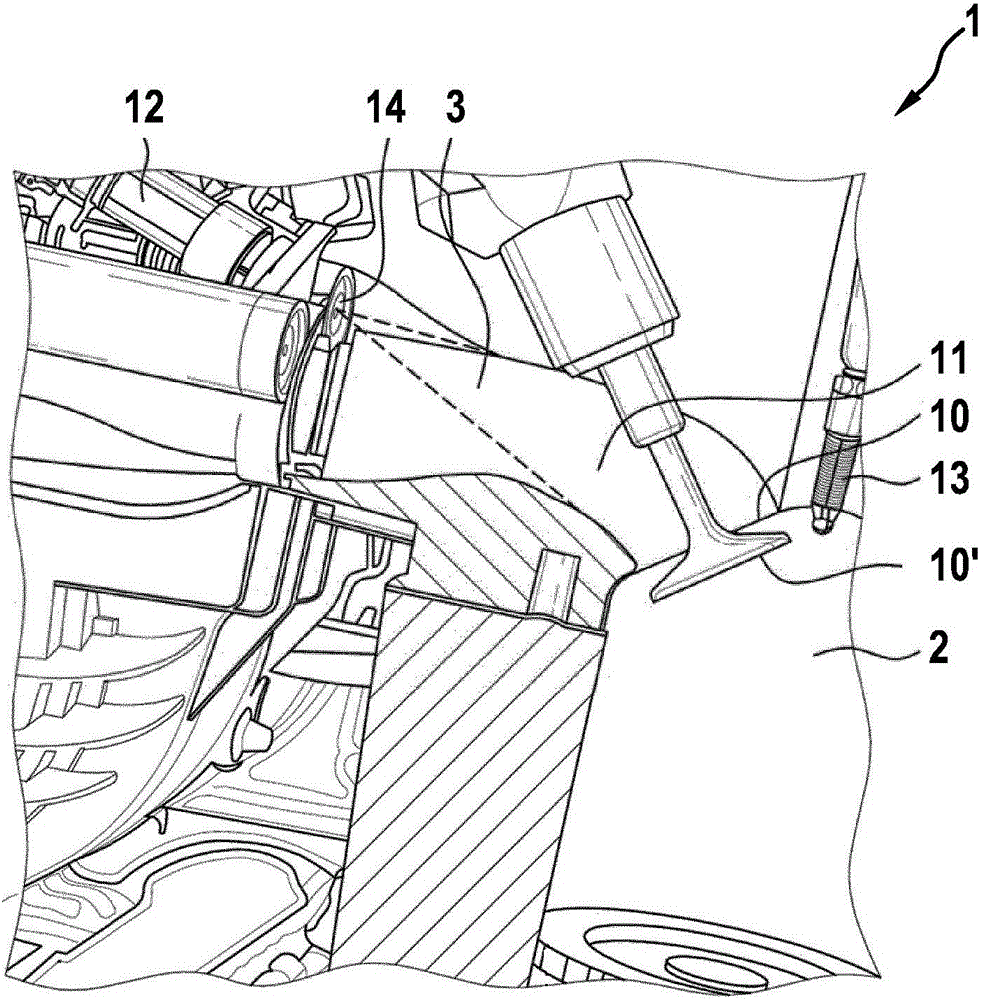
[0023] exist figure 1 shows a diagram of a part of an internal combustion engine 1 comprising a combustion chamber 2, an injection valve 12, an intake valve 10', an ignition device 13, an injection valve port 14, an intake port 10 and a first intake pipe 11, fuel 3 It is injected into the first intake pipe 11 toward the combustion chamber, and the second intake pipe is also provided (in figure 1 not shown). The fuel is atomized in the form of a spray cone when injected, which is figure 1 is shown by dashed lines. It can be seen from this illustration that, in the real embodiment of the internal combustion engine 1 , the fuel 3 is also injected onto the wall of the intake manifold 11 during the injection.

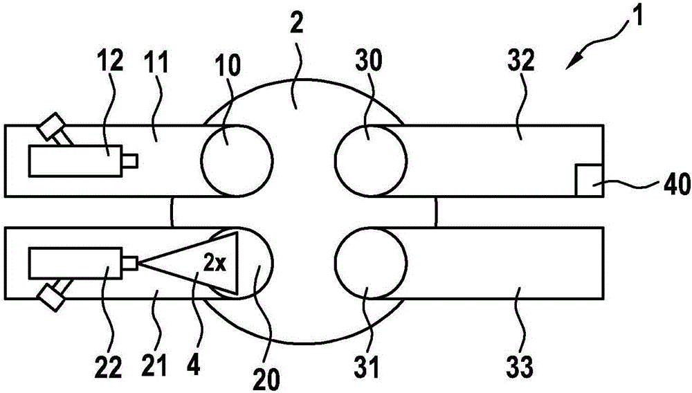
[0024] exist Figure 2a and Figure 2bA schematic illustration of a part of the internal combustion engine 1 which implements the first method step of the method according to an exemplary embodiment of the invention is shown in . The internal combustion engine has a co...


PUM


Abstract

The invention relates to a method for adapting transient compensation on the basis of a lambda-value change to operate an internal combustion engine comprising a combustion chamber. The combustion chamber comprises a first inlet port, connected to a first intake tube, in which tube a first injection valve is arranged. The combustion chamber further comprises a second inlet port, connected to a second intake tube, in which tube a second injection valve is arranged. In a normal mode of operation, a predetermined fuel quantity is injected, the predetermined fuel quantity being composed of a first fuel quantity to be injected through the first inlet valve and a second fuel quantity to be injected through the second inlet valve. In a first method step, the first injection valve remains closed and in a second method step, the first injection valve is opened again, wherein in the second method step, a first test fuel quantity is injected into the combustion chamber via the first inlet port and a second test fuel quantity via the second inlet port, the first test fuel quantity and the second test fuel quantity adding up to the predetermined fuel quantity.

Description

technical field [0001] The invention relates to an internal combustion engine according to the preamble of claim 1 . Background technique [0002] Such internal combustion engines are generally known and are operated by feeding an air-fuel mixture to the combustion chamber during the intake stroke. In order to generate the air-fuel mixture, the injection valve injects and atomizes a predetermined quantity of fuel into the intake pipe, which is connected to the combustion chamber via the intake port. In this case, a throttle valve arranged in the intake manifold determines how much fresh air is sucked into the combustion chamber. As the throttle valve opens, a pressure rise occurs in the intake manifold, whereby the vaporization tendency of the injected fuel is reduced. Together with the fuel which is injected onto the wall of the intake tract, for example by the injection valve, the fuel also accumulates on the wall of the intake tract when the throttle valve is open due t...

Claims


Application Information

Patent Timeline
Patent Type & Authority Applications(China)
IPC IPC(8): F02D41/04F02D41/24F02D41/30
CPCF02D41/047F02D41/2454F02D41/3064F02D41/3094F02D41/3011F02D41/263
Inventor H·哈梅多维克A·古切尔A·克鲁舍A·波塞尔特M·洛伦茨
Owner ROBERT BOSCH GMBH
Learn More