
Speed measurement radar for rail transit

A speed measuring radar, railway track technology, applied in measuring devices, radio wave measurement systems, radio wave reflection/re-radiation and other directions, can solve the problems of low accuracy, short life, frequent replacement, etc., to achieve high accuracy and good stability Effect

Inactive Publication Date: 2015-12-09
ANHUI CHAOYUAN INFORMATION TECH
View PDF2 Cites 1 Cited by
  • Summary
  • Abstract
  • Description
  • Claims
  • Application Information

AI Technical Summary

Problems solved by technology

[0002] Railway track traffic speed measurement radar is developed along with the development of high-speed railways, because the previous railway speed measurement uses photoelectric encoder sensors to measure speed, and they measure speed through the rotation of the wheel shaft. Replacement, low precision and other defects

Method used


Image

  • Speed measurement radar for rail transit
  • Speed measurement radar for rail transit

Examples


Embodiment Construction

[0015] The present invention will be described in further detail below according to the drawings and embodiments.

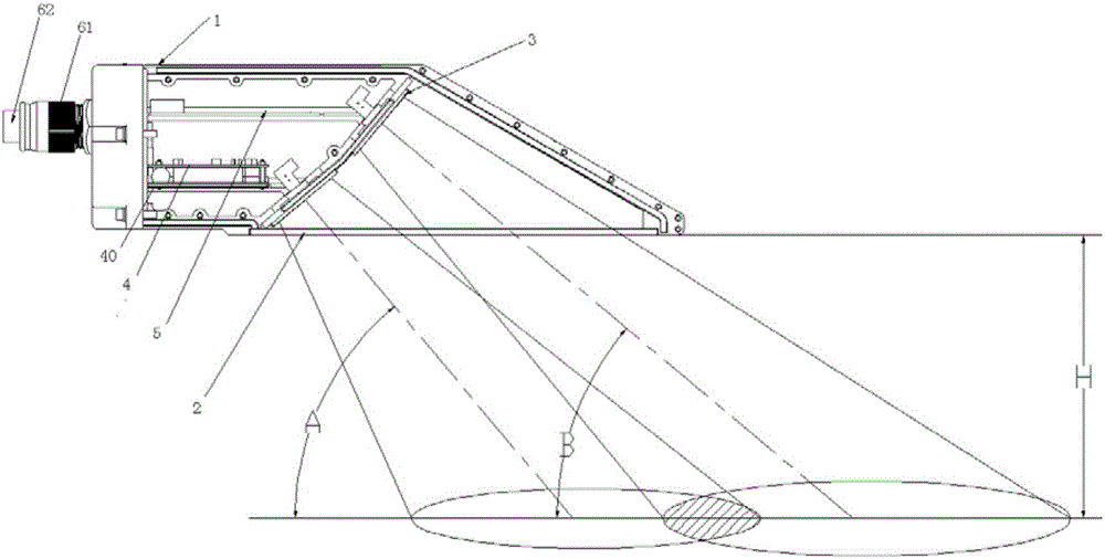
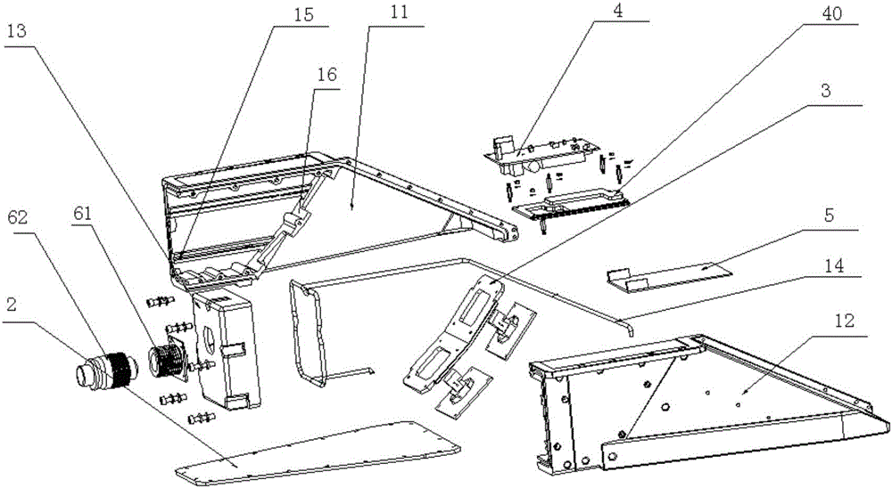
[0016] figure 1 It is a structural schematic diagram of the railway track traffic speed measuring radar of the present invention, figure 2 For the explosion schematic diagram of the railway track traffic speed measuring radar of the present invention, refer to figure 1 , figure 2 , the present invention, the railway track traffic speed measuring radar, comprises housing 1, wave-transmitting board 2, two high-frequency components 3 accommodated in housing, circuit board 4, circuit control board 5, above-mentioned housing 1 bottom opening, opening Install the above-mentioned wave-transmitting plate 2, the transmission signals of the two above-mentioned high-frequency components 3 obliquely pass through the above-mentioned wave-transmitting plate 2, and the emission angles of the two above-mentioned high-frequency components 3 have an included angle, and the inc...


PUM


Abstract

The invention discloses a speed measurement radar for the rail transit, and the radar comprises a housing, a wave-transparent plate, two high-frequency assemblies stored in the housing, a circuit board, and a circuit control board. The bottom of the housing is provided with an opening, and the opening is provided with the wave-transparent plate. Transmission signals of the two high-frequency assemblies pass through the wave-transparent plate in an inclined manner, and the transmission angles of the two high-frequency assemblies form an inclined angle which is within the range from 5 degrees to 15 degrees. The circuit board and the circuit control board are disposed in the housing, and are respectively connected the two high-frequency assemblies. The beneficial effects of the invention lie in that the structure is simple and practical, the radar is not affected by the slipping and idling of wheels, the installation is convenient, and the radar is resistant to dust and water.

Description

technical field [0001] The invention relates to a speed measuring radar, in particular to a speed measuring radar for railway track traffic. Background technique [0002] Railway track traffic speed measurement radar is developed along with the development of high-speed railways, because the previous railway speed measurement uses photoelectric encoder sensors to measure speed, and they measure speed through the rotation of the wheel shaft. Replacement, low precision and other defects. Contents of the invention [0003] The technical problem to be solved by the present invention is to provide a speed measuring radar for railway rail traffic, which has a simple and practical structure, is not affected by wheel slippage and idling, is easy to install, and is dustproof and waterproof. [0004] The present invention is achieved through the following technical solutions. [0005] A railway track traffic speed measuring radar, comprising a housing, a wave-transmitting plate, t...

Claims


Application Information

Patent Timeline
Patent Type & Authority Applications(China)
IPC IPC(8): G01S13/92
CPCG01S13/92
Inventor 林华根王传根陈岩韦勇继邱换春
Owner ANHUI CHAOYUAN INFORMATION TECH
Learn More