Alignment apparatus for shaft coupler installation

A technology for shaft coupling and installation, which is applied in the field of aligning devices for shaft coupling installation, can solve the problems of unrealistic installation, small size of shaft coupling, and difficulty in realizing dial gauge measurement, etc., so as to alleviate the installation and operation space, Avoid field installation effects

Active Publication Date: 2015-12-09
LAIWU IRON & STEEL GRP
View PDF6 Cites 0 Cited by
  • Summary
  • Abstract
  • Description
  • Claims
  • Application Information

AI Technical Summary

Problems solved by technology

Since the dial indicator needs to be installed on-site at the position to be measured through the adjustment rod and the mounting seat, and the size of the above-mentioned equipment is small, the size of the coupling will be correspondingly small, which requires the operator to install the adjustment rod on the docking flange , the operating space of the mounting base and the dial indicator is relatively limited, and even the installation cannot be realized, which eventually makes it difficult to implement the measurement with the dial indicator

Method used


Image

  • Alignment apparatus for shaft coupler installation
  • Alignment apparatus for shaft coupler installation
  • Alignment apparatus for shaft coupler installation

Examples


Embodiment Construction

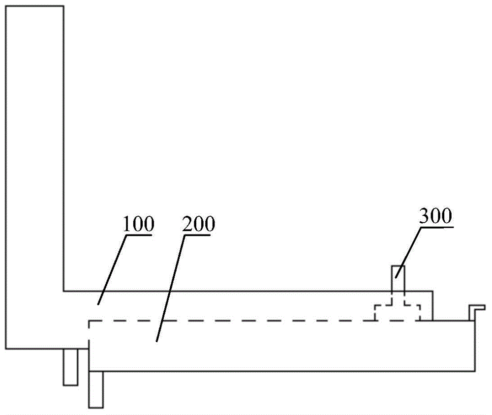
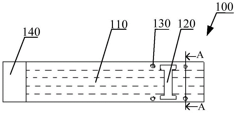
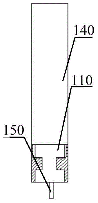
[0039] An embodiment of the present invention provides an alignment device for shaft coupling installation, so as to alleviate the contradiction between the increasingly smaller size of equipment and the large installation and operation space required for on-site installation of dial indicators.

[0040] In order to enable those skilled in the art to better understand the technical solutions in the present invention, the technical solutions in the embodiments of the present invention will be clearly and completely described below in conjunction with the drawings in the embodiments of the present invention. Obviously, the described The embodiments are only some of the embodiments of the present invention, not all of them. Based on the embodiments of the present invention, all other embodiments obtained by persons of ordinary skill in the art without making creative efforts shall fall within the protection scope of the present invention.

[0041] Please refer to Figure 1-10 , ...


PUM


Abstract

Provided in the invention is an alignment apparatus for shaft coupler installation. A guiding hole and a connecting slot connected with the guiding hole are formed in a first support element; a probe is arranged in the guiding hole and can move along the guiding hole; a bottom surface and a top reference surface of the first support element are perpendicular to the moving direction of the probe; and the probe has a first scale segment. A second support element is arranged in the connecting slot in a sliding mode, wherein the sliding direction is perpendicular to the moving direction of the probe. An elastic element is connected with the probe and thus an elastic force enabling the bottom of the probe to be in contact with the top surface of the second support element can be applied to the probe. When the bottom surface of the probe and the top wall of the connecting slot are located at the same plane, a scale reading number in a same plane where a first positive number scale zone of the first scale segment and the top reference surface of the first support element are located expresses an interval between the bottom surface of the first support element and the bottom surface of the second support element at the probe moving direction. According to the scheme, a conflict that the size of equipment is reduced gradually and the large installation operation space is needed when a dial indicator is installed on the spot can be eased.

Description

technical field [0001] The invention relates to the technical field of shaft coupling installation, in particular to an alignment device for shaft coupling installation. Background technique [0002] In the field of mechanical equipment manufacturing, couplings are widely used in equipment connection as a relatively common connection. The coupling consists of two mating flanges. In the process of connecting the two shafts, each butt flange is fixedly connected to the corresponding shaft, and the two butt flanges are then fixedly connected by a bolt assembly, and finally the mutual fixing of the two shafts is realized. In the actual installation process, after the two butt flanges are usually fixed to the corresponding shafts, it is necessary to align the two butt flanges so that the corresponding connection holes on the two butt flanges are aligned, and finally It is convenient for bolts to pass through corresponding connection holes to realize fixed connection. The so-ca...

Claims


Application Information

Patent Timeline
Patent Type & Authority Applications(China)
IPC IPC(8): G01B5/00
Inventor 李雪涛张戈
Owner LAIWU IRON & STEEL GRP
Why Eureka
Try Eureka