An Omnidirectional Motion Spherical Robot
A spherical robot, all-round technology, applied in motor vehicles, transportation and packaging, etc., can solve the problems of limited spherical robot motion performance, limited robot motion performance, inability to eccentric driving torque, etc., achieving easy engineering implementation, simple structure, The effect of simple mechanism principle
- Summary
- Abstract
- Description
- Claims
- Application Information
AI Technical Summary
Problems solved by technology
Method used
Image
Examples
Embodiment 1
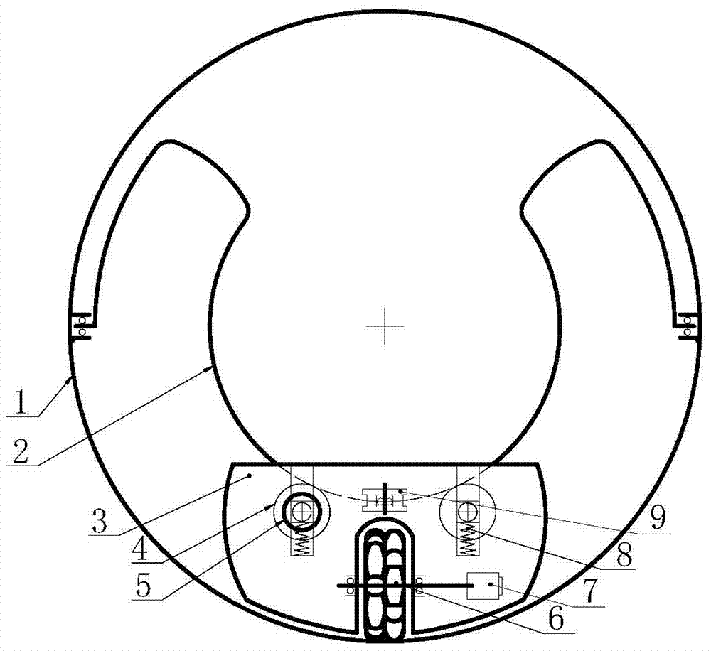
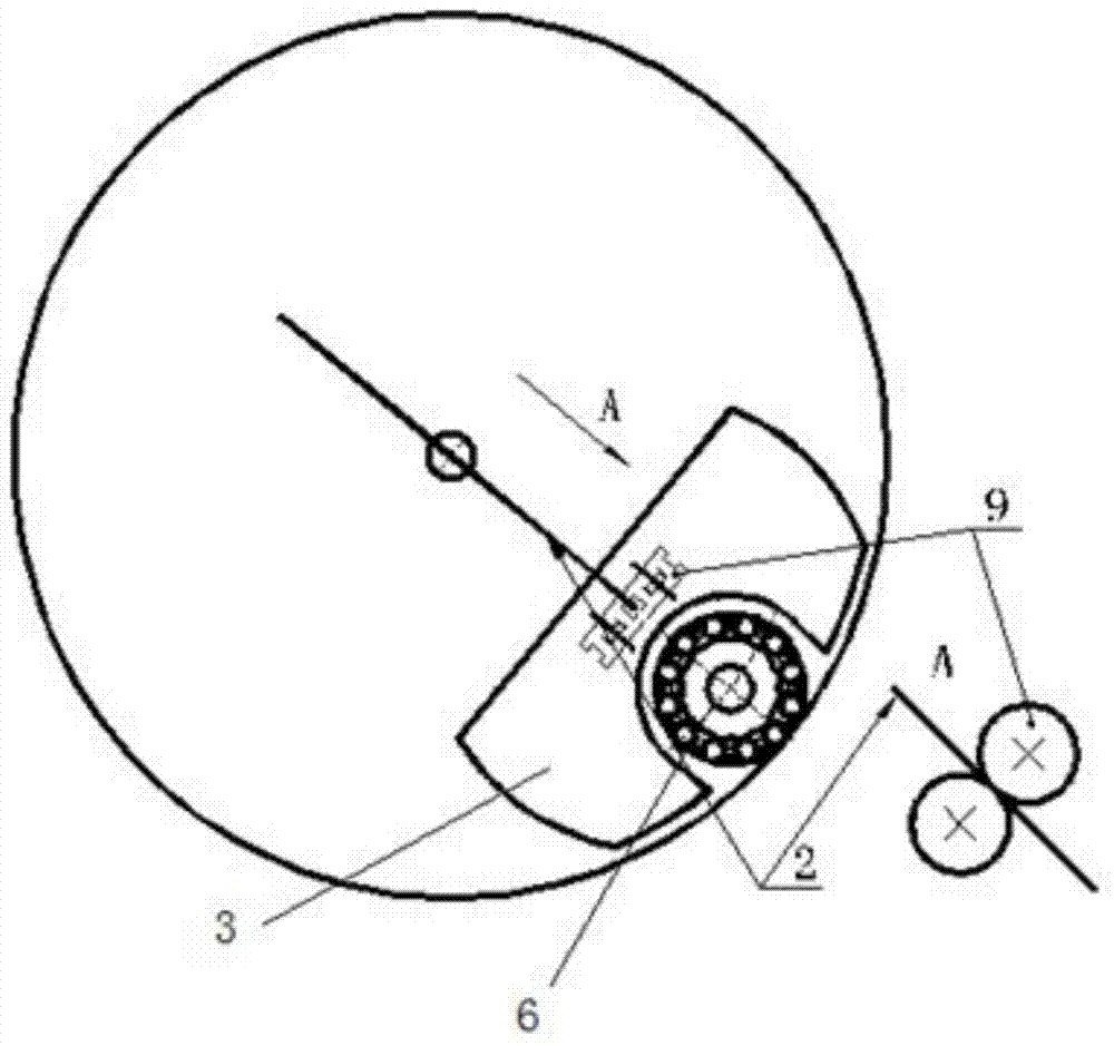
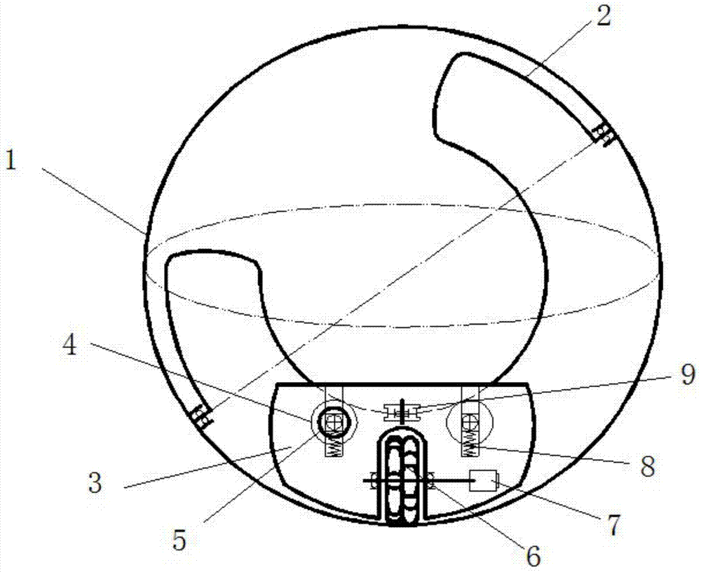
[0031] In order to solve the above-mentioned shortcoming of the prior art, the embodiment of the present invention designs a kind of omni-directional motion spherical robot, such as Figure 1 to Figure 3 As shown, it includes spherical shell 1, arc rail 2, frame 3, rail wheel 4, omnidirectional wheel 6 and guide wheel 9; arc rail 2 is set in spherical shell 1, and both ends of arc rail 2 pass through and support coaxially On the diameter of spherical shell 1; Frame 3 is located in spherical shell 1, and the top of frame 3 is supported on arc track 2 by rail wheel 4 and guide wheel 9; Omnidirectional wheel 6 is installed in the bottom of frame 3.
Embodiment 2
[0033] In order to solve the above-mentioned shortcoming of the prior art, the embodiment of the present invention designs a kind of omni-directional motion spherical robot, such as Figure 1 to Figure 3 As shown, it includes spherical shell 1, arc rail 2, frame 3, rail wheel 4, omnidirectional wheel 6 and guide wheel 9; arc rail 2 is set in spherical shell 1, and both ends of arc rail 2 pass through and support coaxially On the diameter of spherical shell 1; Frame 3 is located in spherical shell 1, and the top of frame 3 is supported on arc track 2 by rail wheel 4 and guide wheel 9; Omnidirectional wheel 6 is installed in the bottom of frame 3. The frame 3 also includes two rail wheels 4, two guide wheels 9, a steering motor 5, a travel motor 7 and a spring 8; the rail wheels 4 are arranged in the frame 3 along the outer circumference of the arc rail 2; the guide wheels 9 Arranged in the frame 3 on the front and rear sides of the arc rail 2; the steering motor 5 is arranged o...
Embodiment 3
[0035] In order to solve the above-mentioned shortcoming of the prior art, the embodiment of the present invention designs a kind of omni-directional motion spherical robot, such as Figure 1 to Figure 3 As shown, it includes spherical shell 1, arc rail 2, frame 3, rail wheel 4, omnidirectional wheel 6 and guide wheel 9; arc rail 2 is set in spherical shell 1, and both ends of arc rail 2 pass through and support coaxially On the diameter of spherical shell 1; Frame 3 is located in spherical shell 1, and the top of frame 3 is supported on arc track 2 by rail wheel 4 and guide wheel 9; Omnidirectional wheel 6 is installed in the bottom of frame 3. The frame 3 also includes two rail wheels 4, two guide wheels 9, a steering motor 5, a travel motor 7 and a spring 8; the rail wheels 4 are arranged in the frame 3 along the outer circumference of the arc rail 2; the guide wheels 9 Arranged in the frame 3 on the front and rear sides of the arc rail 2; the steering motor 5 is arranged o...
PUM
 Abstract
Description
Claims
Application Information
 - R&D
- Intellectual Property
- Life Sciences
- Materials
- Tech Scout
- Unparalleled Data Quality
- Higher Quality Content
- 60% Fewer Hallucinations
Browse by: Latest US Patents, China's latest patents, Technical Efficacy Thesaurus, Application Domain, Technology Topic, Popular Technical Reports.
© 2025 PatSnap. All rights reserved.Legal|Privacy policy|Modern Slavery Act Transparency Statement|Sitemap|About US| Contact US: help@patsnap.com


