Eureka AIR delivers breakthrough ideas for toughest innovation challenges, trusted by R&D personnel around the world.

Short-distance optical magnification module group and near-to-eye display optical module group using the same

An optical amplification and optical module technology, applied in the field of optical instruments

Active Publication Date: 2015-11-25
SHENZHEN DLODLO TECHNOLOGIES CO LTD
View PDF4 Cites 68 Cited by
  • Summary
  • Abstract
  • Description
  • Claims
  • Application Information

AI Technical Summary

Problems solved by technology

[0002] In the prior art, there is no optical magnification module suitable for achieving large magnification within a short distance (less than 5cm), and there is no near-eye display with a super large field of view (FOV) of more than 100 degrees at a short distance (less than 3cm). Optical module

Method used


Image

  • Short-distance optical magnification module group and near-to-eye display optical module group using the same
  • Short-distance optical magnification module group and near-to-eye display optical module group using the same
  • Short-distance optical magnification module group and near-to-eye display optical module group using the same

Examples


Embodiment 1

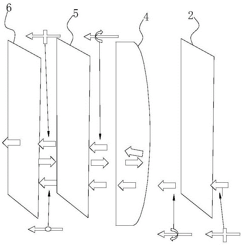
[0026] Such as figure 2 As shown, the near-eye display optical module in the present invention includes a display screen 1, and the display screen 1 is arranged on the side of the first 45-degree phase retarder 2 away from the partially transmissive and partially reflective curved mirror 4, and the display screen 1 and The partially transmissive and partially reflective curved mirrors 4 are respectively arranged on both sides of the first 45-degree phase retarder 2, which can achieve a display effect with a small overall volume but a very large field of view.

[0027] Preferably, the display screen 1 is selected as a miniature high-definition display screen, and in the case of a miniature high-definition display screen, it is possible to see a large field of view and high-definition display effect in a small volume. Preferably, the partially transmissive and partially reflective curved lens 4 is a curved lens with a ratio of 50% transmission and 50% reflection.

[0028] Betw...

Embodiment 2

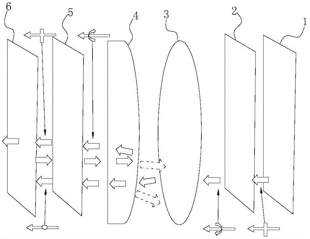
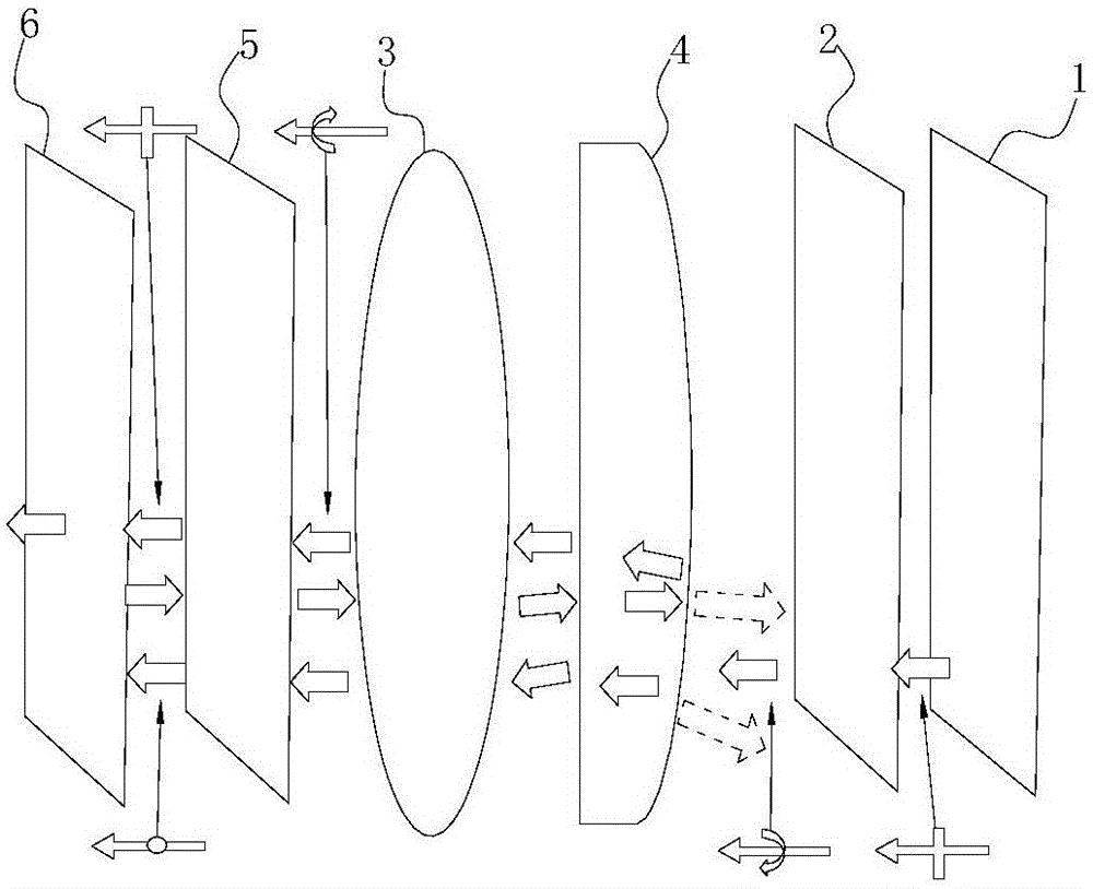
[0035] Such as image 3 As shown, the difference between this embodiment and Embodiment 1 is that the optical devices that do not affect the phase delay of light rays are placed in different positions. Between the two 45 degree phase retarders 5.

Embodiment 3

[0037] Such as Figure 4 As shown, the difference between this embodiment and Embodiment 2 is that the display screen 1, the first 45-degree phase retarder 2, the partially transmissive and partially reflective curved mirror 4, the second 45-degree phase retarder 5 and the reflective polarizer 6 are not coaxial setting.


PUM


Abstract

The invention relates to a short-distance optical magnification module group and a near-to-eye display optical module group using the same and aims at providing an optical magnification module group for realizing high-multiple magnification at a short distance less than 5cm and a near-to-eye display optical module group using the optical magnification module group to realize an extra-large field angle at a short distance less than 3cm. According to the invention, the near-to-eye display optical module group includes a first 45-degree phase delay plate (2), a partial-transmission partial-reflection curve-surface lens (4), a second 45-degree phase delay plate (5) and a reflective polarizing plate (6). In addition, the near-to-eye display optical module group includes a display screen (1) arranged at one side, far away from the partial-transmission partial-reflection curve-surface lens (4), of the first 45-degree phase delay plate (2).

Description

technical field [0001] The invention relates to an optical instrument, in particular to a short-distance optical amplification module and an optical module for near-eye display using the same. Background technique [0002] In the prior art, there is no optical magnification module suitable for achieving large magnification within a short distance (less than 5cm), and there is no near-eye display with a super large field of view (FOV) of more than 100 degrees at a short distance (less than 3cm). Optical modules. Contents of the invention [0003] The technical problem to be solved by the present invention is to provide an optical magnification module that realizes large magnification in a short distance (less than 5cm) and a near-eye display optical module that uses it to realize a super large field of view at a short distance (less than 3cm) . [0004] The short-distance optical amplification module in the present invention includes a first 45-degree phase retarder, a pa...

Claims


Application Information

Patent Timeline
Patent Type & Authority Applications(China)
IPC IPC(8): G02B27/28G02B27/01
CPCG02B27/0172G02B27/286G02B2027/0123G02B27/0101G02B27/283G02B5/3083G02B2027/0118G02B5/003G02B2027/0116G02B2027/013
Inventor 汤伟平李刚张丰学熊旭
Owner SHENZHEN DLODLO TECHNOLOGIES CO LTD
Why Eureka
Eureka Blog
Learn More