
An adjustable lock with fully automatic locking angle and its product

A fully automatic, locking technology, used in travel products, rod connections, components of lighting devices, etc., can solve the problems of cumbersome operation steps, inflexible use, non-adjustment, etc., to achieve simple adjustment operation and market competitiveness. Strong, easy to produce and process

Active Publication Date: 2018-02-06
何洁洁
View PDF8 Cites 0 Cited by
  • Summary
  • Abstract
  • Description
  • Claims
  • Application Information

AI Technical Summary

Problems solved by technology

[0002] At present, the existing locks on the market include the lock body and the fastening parts provided on the lock body, but the angle of the fastening parts is generally fixed and non-adjustable, and the use is inflexible and inconvenient. unable to meet people's needs
For this reason, some manufacturers have developed angle-adjustable locks, but when using this adjustable lock, you first need to manually loosen the lock (such as a butterfly screw), then adjust the angle, and finally tighten the lock; The steps are cumbersome and laborious. When the angle is adjusted incorrectly, the aforementioned operations must be repeated, which is extremely inconvenient and time-consuming

Method used


Image

  • An adjustable lock with fully automatic locking angle and its product
  • An adjustable lock with fully automatic locking angle and its product
  • An adjustable lock with fully automatic locking angle and its product

Examples


Embodiment 1

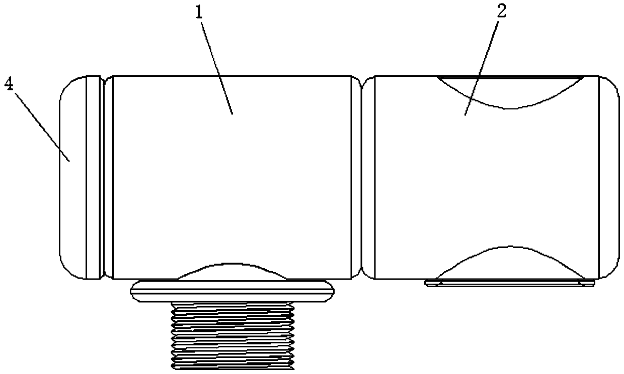
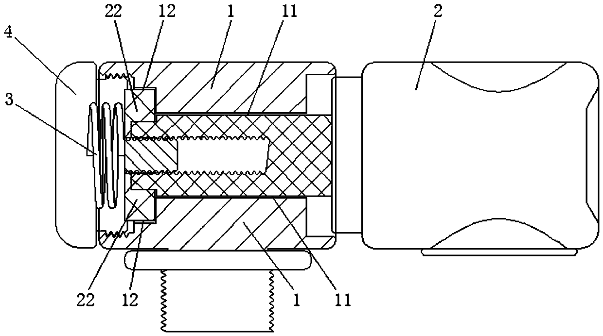
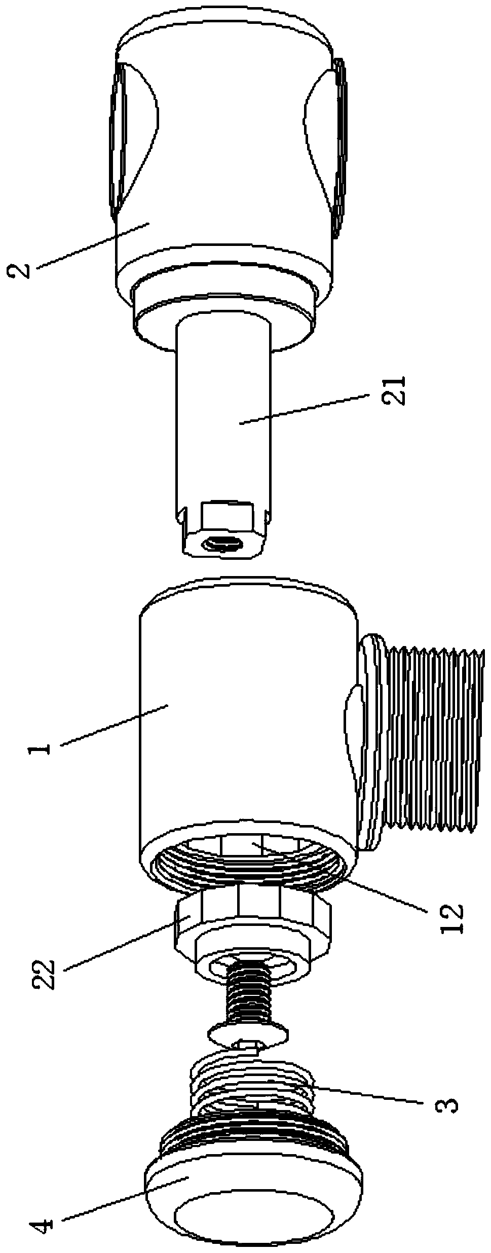
[0039] Such as Figure 1 to Figure 6 As shown in , Embodiment 1 of the present invention provides a fully automatic locking angle adjustable lock, including a lock main body 1 and a rotating buckle 2, the rotating buckle 2 can move axially, rotate to adjust the angle, and automatically It is installed on the lock body 1 in a resetting and locking manner. The specific structure can be as follows: one end of the rotating buckle 2 is provided with a rotating shaft 21, and the lock body 1 is provided with a shaft hole 11 passing through the left and right ends; the rotating shaft 21 is inserted from one end of the shaft hole 11 transversely, The other end of the shaft hole 11 protrudes, and the end is provided with an adjustment and positioning unit 22, which is fixed by screws; The card position 12, the adjustment and positioning unit 22 is stuck in the adjustment card position 12; wherein, the end face of the locking body 1 protruding from the rotating shaft 21 is also provided...

Embodiment 2

[0046] Such as Figure 7 with Figure 8 As shown in , Embodiment 2 of the present invention provides a fully automatic locking angle adjustable lock. Its structure is basically the same as Embodiment 1, including a lock body 1 and a rotating buckle 2. It can be moved and rotated to adjust the angle, and automatically reset and locked on the main body 1 of the lock. The specific structure can be as follows: the lock body 1 is provided with installation through holes 13 that run through the left and right ends, the middle position of the installation through holes 13 is provided with an adjustment card position 12, and the shaft core of the adjustment card position 12 is connected to the installation through hole. 13 have the same shaft core, and the inner diameter of the adjusting card position 12 is smaller than the inner diameter of the installation through hole 13; one end of the rotating buckle 2 is axially movably installed in the installation through hole 13 on the side ...


PUM


Abstract

The invention relates to an adjustable lock catch capable of achieving full-automatic angle locking and a product. The lock catch comprises a lock catch body and a rotating buckle. The rotating buckle can move axially and rotate to adjust the angle and is installed on the lock catch body in an automatic-reset locking manner. In this way, a user can adjust the angle of the rotating buckle on the lock catch at any time, and the angle can be locked automatically; the adjusting operation is quite simple, easy and rapid, and use is quite convenient; and the adjustable lock catch is simple, reasonable and ingenious in structure, easy to produce and machine and high in market competitiveness, and facilitates market development, and therefore business success is obtained.

Description

technical field [0001] The invention belongs to the technical field of locks, and in particular relates to a fully automatic locking angle adjustable lock and its products. Background technique [0002] At present, the existing locks on the market include the lock body and the fastening parts provided on the lock body, but the angle of the fastening parts is generally fixed and non-adjustable, and the use is inflexible and inconvenient. Can't meet people's needs. For this reason, some manufacturers have developed angle-adjustable locks, but when using this adjustable lock, you first need to manually loosen the lock (such as a butterfly screw), then adjust the angle, and finally tighten the lock; The steps are cumbersome and laborious. When the angle is adjusted incorrectly, the aforementioned operations must be repeated, which is extremely inconvenient and time-consuming. Contents of the invention [0003] In order to solve the above-mentioned technical problems existing...

Claims


Application Information

Patent Timeline
Patent Type & Authority Patents(China)
IPC IPC(8): F16B7/08F16B7/18A45B9/00A45B25/00E04H15/34F21V21/00
CPCA45B9/00A45B25/00E04H15/34F16B7/18F21V21/00
Inventor 何洁洁
Owner 何洁洁
Learn More