
Fan and air outlet structure

A technology of electric fans and fan blades, which is applied to parts of pumping devices for elastic fluids, non-variable pumps, machines/engines, etc., can solve problems affecting human comfort, achieve simple structure, low cost, The effect of increasing the wind outlet angle

Active Publication Date: 2018-09-07
GREE ELECTRIC APPLIANCES INC
View PDF6 Cites 2 Cited by
  • Summary
  • Abstract
  • Description
  • Claims
  • Application Information

AI Technical Summary

Problems solved by technology

[0003] However, the way of turning the fan blades or deflectors is to completely change the flow direction of the wind field, that is, there is only wind at a certain angle directly opposite the wind outlet. After the direction is changed, there is no or little wind here, which affects the comfort of the human body.

Method used


Image

  • Fan and air outlet structure
  • Fan and air outlet structure
  • Fan and air outlet structure

Examples


Embodiment Construction

[0044] The present invention will be described in further detail below in conjunction with the accompanying drawings and specific embodiments, but not as a limitation of the present invention.

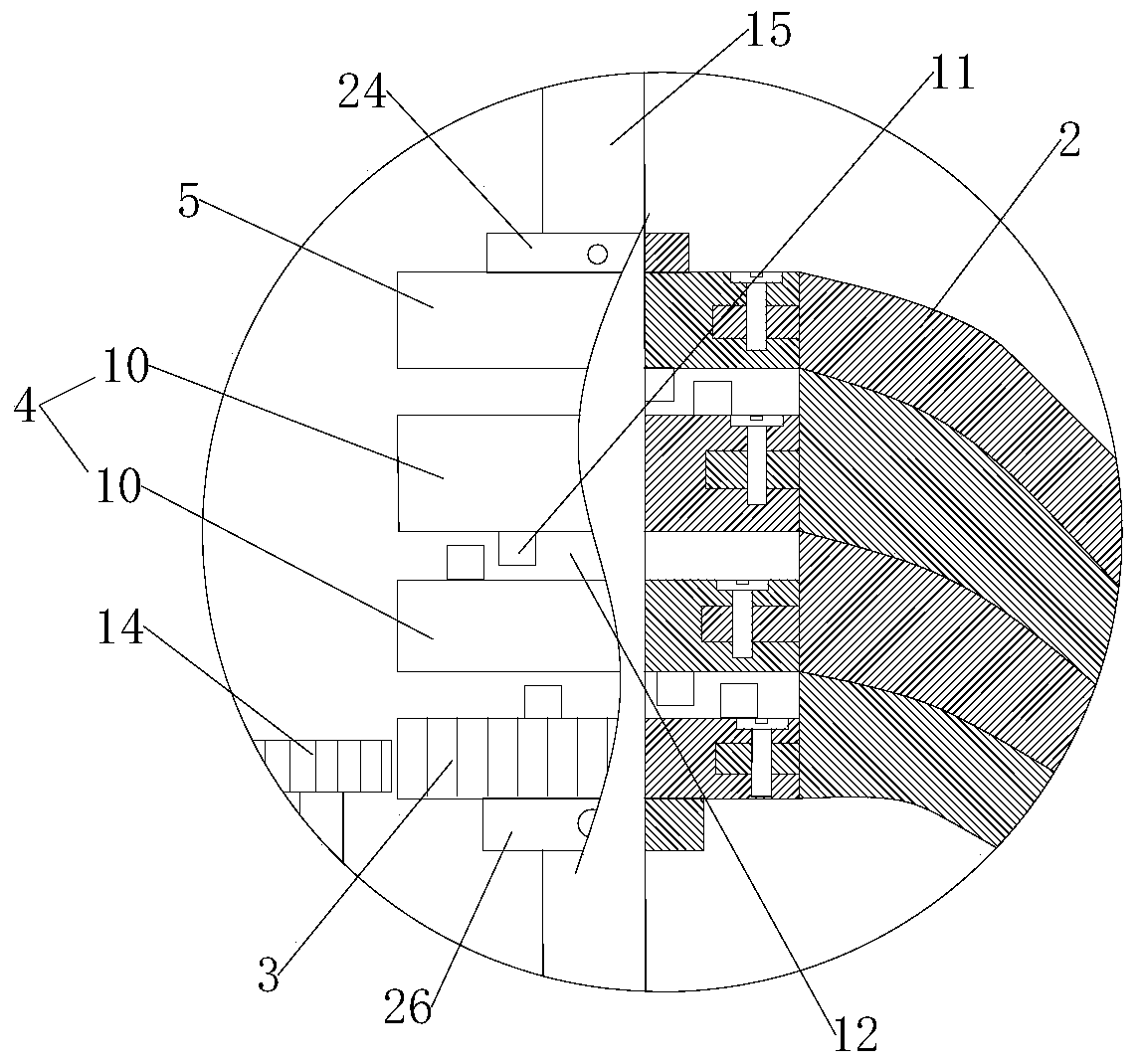
[0045] Please refer to Figure 1 to Figure 21 , the embodiment of the present invention provides an air outlet structure, which can be used in devices such as electric fans. The wind outlet structure includes: a driving device 1; a plurality of wind deflectors 2; a linkage mechanism 30, which is connected with the driving device 1 and a plurality of wind deflectors 2, and the driving device 1 drives a plurality of wind deflectors 2 to move successively through the linkage mechanism , preferably, the movement may refer to the sequential opening or closing of a plurality of windshields 2 . Preferably, the windshield 2 may be curved or straight. In one embodiment, one end of the windshield 2 is fixed to the linkage mechanism 30, and the other end is connected to the edge of the fan casi...


PUM


Abstract

The invention discloses an electric fan and an air outlet structure. The air outlet structure comprises a drive device, a plurality of wind shields and a linkage mechanism connected with the drive device and the wind shields. The wind shields are driven by the drive device to sequentially move through the linkage mechanism. As the structure is adopted, the wind shields can be made to move in sequence through the linkage mechanism, accordingly the air outlet angle is adjusted through the opening degree of the wind shields, and the air outlet angle is increased. The defect that when a conventional electric fan in the prior art steers, a wind field is instable is overcome, the electric fan can output air stably and conveniently with a large angle, and people feel comfortable. The beneficial effects of being simple in structure and low in cost are achieved.

Description

technical field [0001] The invention relates to the field of electric fans, in particular to an electric fan and an air outlet structure. Background technique [0002] At present, conventional electric fans mainly have two ways to obtain a larger air outlet angle: one is to allow the fan to rotate partly, that is, a rotary blade fan; the other is to change the direction of air flow through the rotation of the wind deflector. [0003] However, the way of turning the fan blades or deflectors is to completely change the flow direction of the wind field, that is, there is only wind at a certain angle directly opposite the wind outlet. After the direction is changed, there is no or little wind here, which affects the comfort of the human body. . Contents of the invention [0004] Embodiments of the present invention provide an electric fan and an air outlet structure with simple structure, low cost, adjustable air outlet angle and stable wind field. [0005] In order to solve...

Claims


Application Information

Patent Timeline
Patent Type & Authority Patents(China)
IPC IPC(8): F04D29/40
Inventor 何国军魏亮
Owner GREE ELECTRIC APPLIANCES INC
Learn More