Clutch lock

A clutch lock and clutch pin technology, which is applied in the field of clutch locks, can solve problems such as the lock cannot be opened, the clutch pin cannot be realized, and the rear lock cylinder cannot be driven, so as to improve reliability and solve the effect of not being able to unlock the lock

Inactive Publication Date: 2015-11-04
GUANGDONG JINDIAN ATOM LOCK
View PDF7 Cites 0 Cited by
  • Summary
  • Abstract
  • Description
  • Claims
  • Application Information

AI Technical Summary

Problems solved by technology

There are certain deficiencies in the structure of this lock. Sometimes the sleeve cannot drive the rear lock cylinder so that the clutch pin cannot be controlled and the engagement of the front and rear lock cylinders cannot be realized, resulting in the lock not being opened.

Method used


Image

  • Clutch lock
  • Clutch lock
  • Clutch lock

Examples


Embodiment 1

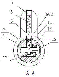
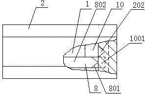
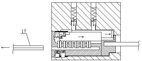
[0015] See figure 1 — image 3 , the clutch lock of the present invention includes a lock body 2, a rotatable lock core 1 and a clutch seat 10 are arranged axially in the lock body 2, and a number of two blade pins 12 and their return positions are arranged on the lock core 1 along the axis. The spring 19 is a set of blade pins, and the blade pins 12 are provided with V-shaped grooves; the lock core 1 and the clutch seat 10 are respectively provided with corresponding locking side column grooves 101 and clutch pin slide grooves 1001, and the locking side column grooves 101 and the clutch pin chute 1001 are respectively provided with a locking side column 11 and a clutch pin 8 with a handle 802. The locking side column 11 can be matched with the V-shaped groove on the blade pin 12, and the locking side column 11 is provided with a step shaped groove 1101, the upper part of the locking side column groove 101 is fixed with the card 4 that matches the stepped groove 1101 on the l...


PUM


Abstract

The invention discloses a clutch lock, comprising a lock body, a lock cylinder which is axially sleeved in the lock body and can rotate, and a clutch base, and the lock cylinder is provided with a plurality of blade marbles with V-shaped grooves along an axis, and the blade marbles are elastic. The lock cylinder and the clutch base are respectively provided with a locking side column which is cooperated with the V-shaped groove on the blade marble and has elasticity, and a clutch pin with a clamping handle. The end of the clutch pin is a wedge shape. The clamping handle of the clutch pin is between the locking side column and the lock body. The lock body is provided with a clamping groove matched with the clamping handle of the clutch pin, and a wedge-shaped clamping groove cooperated with the wedge-shaped end of the clutch pin. The lock body is internally provided with a clutch pin clamping bead which contacts with the clutch pin in a radial manner and has elasticity. Since the clutch pin with the clamping handle is used, when the lock cylinder rotates, the lock cylinder joins with the clutch base through the clamping handle of the clutch pin, so as to achieve an objective of unlocking. The structure can greatly improve reliability of clutch of the lock cylinder and the clutch base, and a problem that a lock cannot be opened is thoroughly solved.

Description

technical field [0001] The invention belongs to locks, in particular to a clutch lock. Background technique [0002] In the existing lock, the lock cylinder of a kind of lock can rotate freely when in the locked state, so as to prevent the lock cylinder from being broken by inserting the lock cylinder with a tool and forcefully destroying the pins of the lock cylinder to open the lock. The lock core of this lock is composed of front and rear lock cores. The front lock core is connected with the rear lock core with elastic beads through the sleeve. When unlocking, the front lock core and the sleeve drive the rear lock core to control the clutch pin to realize The clutch of the rear lock cylinder. There are certain deficiencies in the structure of this lock. Sometimes the sleeve cannot drive the rear lock core so that the clutch pin cannot be controlled and cannot realize the engagement of the front and rear lock cores, resulting in the lock not being opened. Contents of th...

Claims


Application Information

Patent Timeline
Patent Type & Authority Applications(China)
IPC IPC(8): E05B29/00E05B15/00
Inventor 雷先鸣涂永芳潘安宏
Owner GUANGDONG JINDIAN ATOM LOCK
Why Eureka
Try Eureka