Eureka AIR delivers breakthrough ideas for toughest innovation challenges, trusted by R&D personnel around the world.

Lamp structure

A lamp and lampshade technology, which is applied in the field of lamp structure with reflectors, can solve problems such as glare, and achieve the effects of improving glare, improving heat dissipation efficiency and reliability.

Inactive Publication Date: 2015-10-14
GENESIS PHOTONICS
View PDF4 Cites 2 Cited by
  • Summary
  • Abstract
  • Description
  • Claims
  • Application Information

AI Technical Summary

Problems solved by technology

[0005] In view of the problems of the above-mentioned existing lighting fixtures, the object of the present invention is to provide a lighting fixture structure to improve the problem of glare caused by the existing lighting fixtures

Method used


Image

  • Lamp structure
  • Lamp structure
  • Lamp structure

Examples


Embodiment Construction

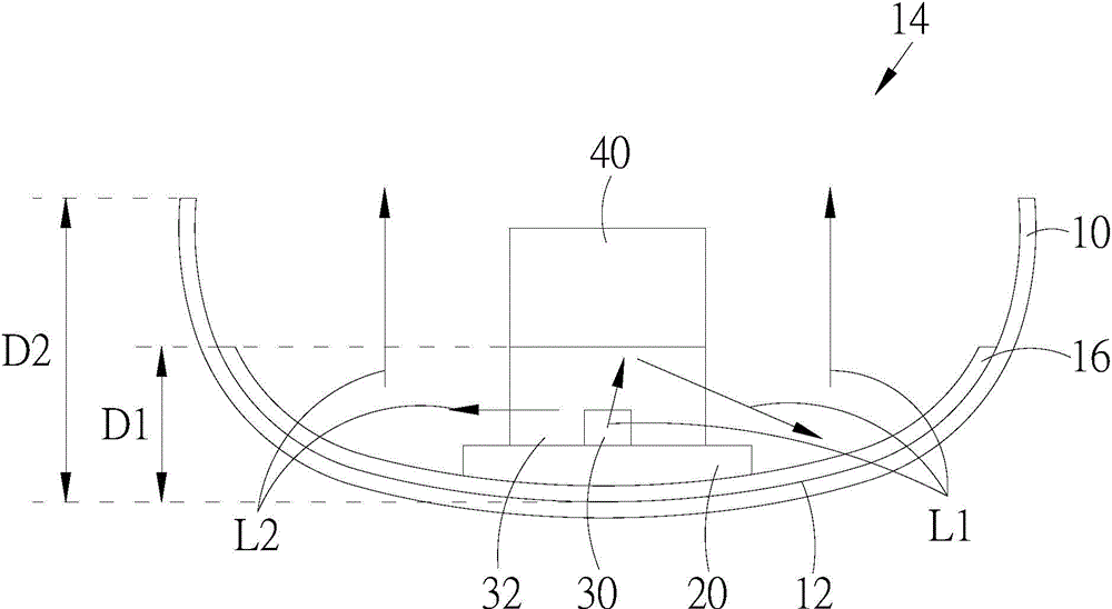
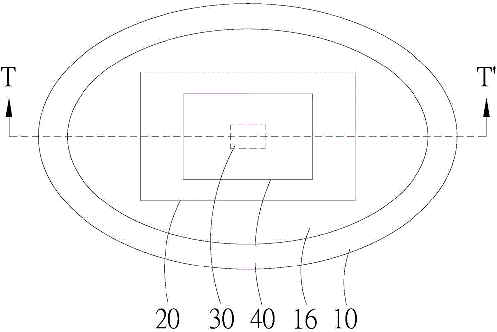
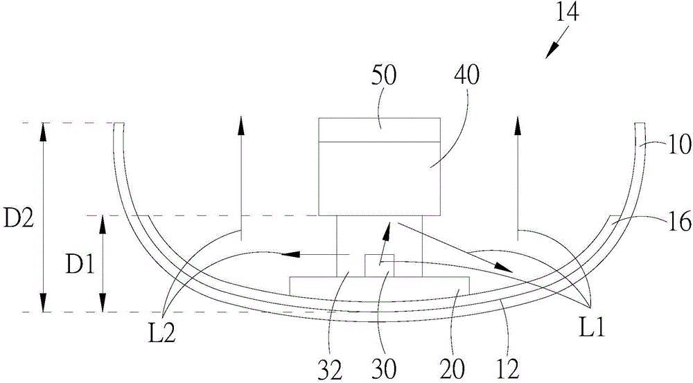
[0059] see figure 1 and figure 2 , figure 1 It is a schematic cross-sectional view of the first preferred embodiment of the lamp structure of the present invention, figure 2 for figure 1 The upper view of the first preferred embodiment of the lamp structure of the present invention. Such as figure 1 and figure 2 As shown, the lamp structure of the present invention includes: a lampshade 10 , a substrate 20 , at least one light emitting unit 30 and a reflector 40 . The lampshade 10 has a bottom side 12 and a light emitting side 14 opposite to each other, and the bottom side 12 is provided with a reflective layer 16 . The base plate 20 is arranged on the underside 12 of the lampshade 10 . The light emitting unit 30 is disposed on the substrate 20 to emit a plurality of light rays L1, L2. The reflector 40 is arranged above the light emitting unit 30. In the first preferred embodiment of the lamp structure of the present invention, the reflector 40 is arranged on a pack...


PUM


Abstract

A lamp structure is disclosed. The lamp structure includes: a lamp cover having a bottom side and light-emitting side opposing to the bottom side, a reflection layer being disposed on the bottom layer; a substrate disposed on the bottom side of the lamp cover; at least one light-emitting unit disposed on the substrate to emit a plurality of light beams; and a reflection member disposed above the light-emitting unit. The light beams are at least reflected by the reflection layer of the lamp cover, and are emitted from the light-emitting side of the lamp cover.

Description

technical field [0001] The invention relates to a lamp structure, in particular to a lamp structure with a reflector. Background technique [0002] Light-emitting diodes (LEDs) have excellent characteristics such as small size, low power consumption, shock resistance, fast response, long life, environmental protection and mercury-free, and due to the rising awareness of environmental protection and energy saving in recent years, light-emitting diodes have been widely used in various on lighting equipment. [0003] However, because the LED emits light, it will also generate a lot of heat. The accumulation of these heat will cause serious light decay of the LED in a high temperature environment, which will affect the brightness and life of the LED. [0004] Moreover, since people now have higher and higher requirements for lighting fixtures, if the light is directly emitted by the lighting fixtures, it may cause glare and affect the health of human eyes. Contents of the inv...

Claims


Application Information

Patent Timeline
Patent Type & Authority Applications(China)
IPC IPC(8): F21S2/00F21V7/00F21V7/22F21V17/10F21V29/89
CPCF21V7/0066F21K9/50F21V3/0472F21V17/101F21V29/70F21S2/00F21V7/0008F21V7/22F21V17/10F21V29/00F21V7/0025H01L21/02107F21Y2105/10F21K9/60F21Y2115/10F21V7/24F21V7/28
Inventor 陈正言
Owner GENESIS PHOTONICS
Why Eureka
Eureka Blog
Learn More