
Flat pneumatic tyre

A technology for pneumatic tires and tires, which is applied to the reinforcement layer, tire parts, tire edges and other directions of pneumatic tires, can solve the problems of complex manufacturing process, intensive material consumption, personnel and equipment, and achieves small circumferential deformation and guaranteed load bearing. Demand, the effect of low heat generation

Inactive Publication Date: 2015-10-07
李智盛
View PDF5 Cites 1 Cited by
  • Summary
  • Abstract
  • Description
  • Claims
  • Application Information

AI Technical Summary

Problems solved by technology

However, because this technology cannot overcome the problems of complex manufacturing process, large material consumption, intensive personnel and equipment, and local stress concentration caused by the stress and strain of the tire under load conditions, it is easy to cause early damage.

Method used


Image

  • Flat pneumatic tyre

Examples


Embodiment Construction

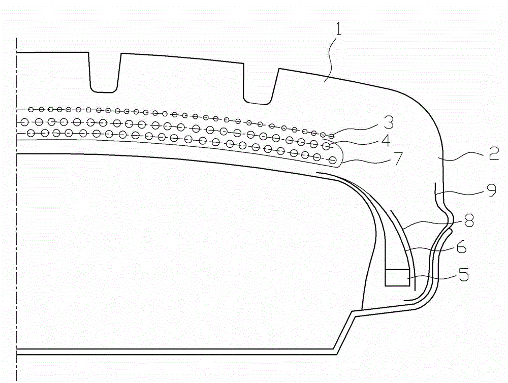
[0022] Such as figure 1 As shown, in a flat pneumatic tire, the tire body includes a crown portion 1 and a bead portion 2, and the tire body is provided with a cap layer 3, a belt layer 4, a bead wire 5 and a wire ring 6, and the tire body It consists of two parts, the crown part 1 and the bead part 2. The cap layer 3 and the belt layer 4 are arranged on the crown part 1, and a stress balance layer 7 is arranged under the belt layer 4. The stress balance layer 7 The two ends are wrapped around the end of the belt layer 4 and sandwiched between the cap layer 3 and the belt layer 4, and the two ends of the traveler cloth 6 are overlapped and overlapped under the edge of the stress balance layer 7 .

[0023] The bead portion 2 is provided with a bead reinforcing layer 8 , and the bead reinforcing layer 8 is attached to the outer side of the flipper 6 .

[0024] The bead portion 2 is provided with a chafer 9 along its outer edge.

[0025] The stress balance layer is made of fib...


PUM


Abstract

The invention discloses a flat pneumatic tyre. A tyre body comprises a tyre crown part (1) and a tyre bead part (2), and a cap ply (3), a belt ply (4), a bead wire (5) and a bead chafer (6) are arranged in the tyre body. The flat pneumatic tyre is characterized in that the tyre body consists of the tyre crown part (1) and the tyre bead part (2), wherein the cap ply (3) and the belt ply (4) are arranged at the tyre crown part (1); a stress balancing ply (7) is arranged under the belt ply (4); both ends of the stress balancing ply (7) are wrapped at the ends of the belt ply and clamped between the cap ply (3) and the belt ply (4); both ends of the bead chafer (6) are overlapped and in overlap connection under the edge of the stress balancing ply (7). Through the adoption of the flat pneumatic tyre, the usability of the tyre is comprehensively improved, the material consumption is greatly reduced, and the manufacturing process is further optimized.

Description

technical field [0001] The invention relates to tires, in particular to an ultra-flat pneumatic tire. Background technique [0002] The used tires of motor vehicles usually have the most excellent performance of pneumatic tires. Pneumatic tire technology changes have gone through three stages, namely: bias structure tires, belted bias structure tires and radial structure tires. The common technical feature of the above-mentioned structures is that the section height of the tire is relatively high, and the deformation of the tire is relatively large during use. Designers try to take measures for integration from the aspects of tire shape, material layout, manufacturing process and professional equipment, in order to ensure the quality of tires. However, because this technology cannot overcome the problems of complex manufacturing process, large material consumption, intensive personnel and equipment, and local stress concentration generated by the stress and strain of the ...

Claims


Application Information

Patent Timeline
Patent Type & Authority Applications(China)
IPC IPC(8): B60C9/18B60C15/04
Inventor 李智盛李兆友冯真
Owner 李智盛
Learn More