Wind driven generator rotating blade and wind driven generator adopting the same

A technology of wind generators and rotating blades, which is applied in the direction of wind turbines, wind turbines, and wind motors at right angles to the wind direction, which can solve the problems of severe blade shaking, long residence time, and high safety hazards, and achieve reduced shaking and enhanced wind power. Stability, the effect of enhancing balance and stability

Active Publication Date: 2015-09-30
杰米伊罗德里格斯 +1
View PDF11 Cites 4 Cited by
  • Summary
  • Abstract
  • Description
  • Claims
  • Application Information

AI Technical Summary

Problems solved by technology

[0003] The purpose of the present invention is to address the reverse resistance wind existing in the rotating blades of the spiral wind generator in the prior art described in the background technology for a long time on the opposite side of the blades, the negative work on the blades is too large, the blades shake seriously, and the power generation efficiency is reduced. Low, easy damage to the motor, high potential safety hazards, etc., to provide a wind turbine rotating blade that can solve the aforementioned problems

Method used


Image

  • Wind driven generator rotating blade and wind driven generator adopting the same
  • Wind driven generator rotating blade and wind driven generator adopting the same
  • Wind driven generator rotating blade and wind driven generator adopting the same

Examples


Embodiment Construction

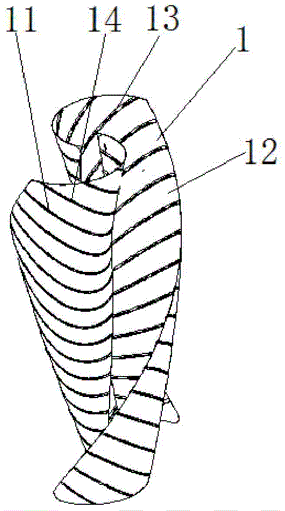
[0020] Such as figure 1 A rotating blade of a wind power generator is shown, which includes an integrally formed helical blade body 1, and on the back of the blade body 1, a plurality of reverse wind guiding grooves 11 at a certain angle to the horizontal direction are distributed at a certain interval. On the front of the blade body 1 between the positions of the reverse wind guide grooves 11, a plurality of transverse positive wind guide grooves 12 are formed, and in the reverse wind guide grooves 11, several holes penetrating the blade body are arranged. Reverse ventilation holes 13, when the wind blows from the front of the blade body 1, it acts on the positive wind guide groove 12, pushing the blade body 1 to rotate, while the reverse resistance wind will move to the reverse wind guide on the back of the blade body 1 In the groove 11 , it leaves the fan blade body 1 through the reverse ventilation hole 13 in the reverse wind guide groove 11 .

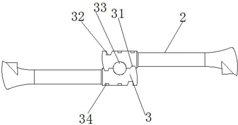
[0021] Such as image 3 A...


PUM


Abstract

The invention discloses a wind driven generator rotating blade. The blade comprises a helical blade body which is integrally formed, multiple reverse direction air guide grooves are formed in the back side of the blade body at a certain angle relative to the horizontal direction in a mode that the grooves are distributed at intervals, multiple transverse positive direction air guide grooves are formed in the front side, among the reverse direction air guide grooves, of the blade body, multiple reverse direction vent holes penetrating through the blade body are formed in the reverse direction air guide grooves, when air is blown from the front side of the blade body, action is produced into the positive direction air guide grooves, and the blade body is propelled to rotate, while reverse direction resistance air at the back side of the blade body moves into the reverse direction air guide grooves and leaves the blade body through the reverse direction vent holes in the reverse direction air guide grooves. A wind driven generator is further disclosed. The wind driven generator comprises a generator body, a base, a revolving shaft and two wind driven generator rotating blades, the wind driven generator rotating blades are fixedly connected to the revolving shaft, double helix cooperation is formed between the two wind driven generator rotating blades, the revolving shaft is fixedly connected with the base, the lower end of the blade body is fixedly connected with the base, and the lower end of the revolving shaft is connected with the generator body.

Description

technical field [0001] The invention relates to the field of wind power generation equipment, in particular to a wind power generator rotating blade. Background technique [0002] Traditional wind turbines usually use materials that are light in density and have the best fatigue strength and mechanical properties, and can withstand extreme harsh conditions such as storms and random loads; the material of the blade must ensure a smooth surface to reduce wind resistance, rough The surface of the blade will also be torn by the wind. Traditional wind blades are usually long strips, which are suitable for use in areas with sufficient wind resources. With the development of wind power technology, a wind turbine with spiral blades has been developed. The blades of traditional wind turbines are twisted, and two blades are used to form double-helical blades, which can increase the wind energy utilization coefficient of wind turbines. When the wind turbine is running, the concave par...

Claims


Application Information

Patent Timeline
IPC IPC(8): F03D3/06F03D9/00
CPCY02E10/74
Inventor 杰米伊罗德里格斯
Owner 杰米伊罗德里格斯
Why Eureka
Try Eureka