High Thrust Servo Electric Cylinder

A servo electric cylinder and high thrust technology, applied in the direction of electrical components, electromechanical devices, electric components, etc., can solve the problems of easy free rotation of screw or screw nut, small thrust, high cost of use, etc., to improve stability and Practicality, improved output thrust, and low manufacturing cost

Inactive Publication Date: 2017-09-22
嘉兴市海创通用设备有限公司
View PDF9 Cites 0 Cited by
  • Summary
  • Abstract
  • Description
  • Claims
  • Application Information

AI Technical Summary

Problems solved by technology

The traditional high-thrust servo electric cylinder has the following defects: first, the thrust is small, the thrust is limited and the thrust is difficult to reach more than 35 tons, the price is expensive and the cost of use is high; second, the structure is complex, and the screw or screw nut is prone to damage. free rotation
[0004] Although the above-mentioned solution has the above advantages, it still has at least the following defects: it still fails to improve the above-mentioned technical problems that the thrust is small and the screw rod or screw nut is prone to free rotation, and the manufacturing requirements are high and the practicability is poor.

Method used


Image

  • High Thrust Servo Electric Cylinder
  • High Thrust Servo Electric Cylinder
  • High Thrust Servo Electric Cylinder

Examples


Embodiment 1

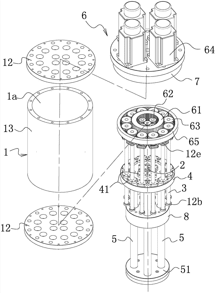
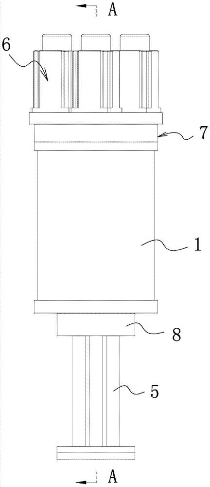
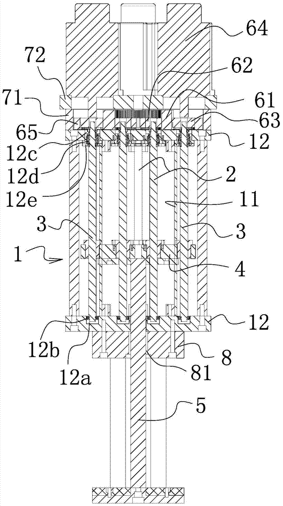
[0031] Such as Figure 1-6 As shown, the high-thrust servo electric cylinder includes a cylinder body 1 with a chamber 1a. The cylinder body 1 is provided with a number of inner screw rods 2 that are respectively pierced in the chamber 1a and are evenly distributed on the circumference so as to form a circle. The inner screw mandrel 2 enclosed in a circle is provided with an outer screw mandrel 3 which is evenly distributed in a number of circles so as to form at least one circle. on the push plate 4, and the inner screw rod 2 is threadedly connected with the push plate 4, and the outer screw rod 3 is threaded with the push plate 4, and a plurality of inner screw rods 2 and outer screw rods 3 are provided on the push plate to penetrate one by one. The screw guide sleeve 41 is provided with an internal thread on the inner wall of the screw guide sleeve, and the inner screw rod 2 and the outer screw rod 3 are connected with the internal thread threads of the corresponding screw ...

Embodiment 2

[0041] Such as Figure 7 As shown, the structure and principle of the present embodiment are basically the same as those of the first embodiment, which will not be repeated here. The difference is that the driving structure is a multi-point meshing flexible transmission device 66 . The multi-point meshing flexible transmission device is arranged at one end of the cylinder body.


PUM


Abstract

The invention belongs to the precise mechanical power source technical field and relates to a novel large-thrust servo electric cylinder. With the novel large-thrust servo electric cylinder adopted, technical problems in the prior art such as low thrust and poor practicability can be solved. The novel large-thrust servo electric cylinder of the invention comprise a cylinder body with a chamber; the cylinder body is provided with a plurality of inner screw rods which extend into the chamber and are distributed uniformly and circumferentially so as to form one circle through surrounding; outer screw rods which are distributed uniformly and circumferentially so as to form at least one circle through surrounding are arranged at the outer periphery of the inner screw rods which form one circle through surrounding; the inner screw rods and the outer screw rods respectively pass through a push plate in the chamber; the inner screw rods are in threaded connection with the push plate; the outer screw rods are also in threaded connection with the push plate; the push plate is provided with at least one push rod which can move relative to the cylinder body; and the cylinder body is provided with a driving mechanism which can drive the inner screw rods and the outer screw rods to rotate synchronously. Compared with the prior art, the novel large-thrust servo electric cylinder of the invention has the advantages of large thrust and high practicability.

Description

technical field [0001] The invention belongs to the technical field of precision mechanical power sources, in particular to a large-thrust servo electric cylinder. Background technique [0002] The high-thrust servo electric cylinder is a mechanical device that can generate a power source, and is currently widely used in mechanical equipment in various fields. For example: mechanical equipment such as full servo electric injection molding machines and presses. The structure of the traditional high-thrust servo electric cylinder includes a cylinder body and a screw rod installed in the cylinder body. A screw nut is sleeved on the screw rod. The screw nut is connected to the piston rod. The drive motor drives the screw rod to rotate, and the screw rod The nut walks on the screw rod to make the piston rod move, and an anti-rotation guide groove is provided in the cylinder body to prevent the screw nut from rotating. The traditional high-thrust servo electric cylinder has the ...

Claims


Application Information

Patent Timeline
Patent Type & Authority Patents(China)
IPC IPC(8): H02K7/06H02K7/10
Inventor 钱德林杨虎李毅
Owner 嘉兴市海创通用设备有限公司
Why Eureka
Try Eureka