
Pitch angle adjusting device of picture frame

An angle adjustment device and mirror frame technology, applied in the directions of transmission devices, electromechanical devices, electric components, etc., can solve the problems of unstable optical element angle, repeated positioning accuracy decline, dead zone of guide rail mechanism, etc., and achieve simple structure and angle repair ability. Strong, high-precision effects

Active Publication Date: 2015-09-09
SHANGHAI INST OF OPTICS & FINE MECHANICS CHINESE ACAD OF SCI
View PDF5 Cites 5 Cited by
  • Summary
  • Abstract
  • Description
  • Claims
  • Application Information

AI Technical Summary

Problems solved by technology

It is designed to solve the problems of angular drift of optical components caused by the instability of the limit of the spring mechanism, and the dead zone of the reciprocating motion of the guide rail mechanism, resulting in a decrease in repeat positioning accuracy.

Method used


Image

  • Pitch angle adjusting device of picture frame
  • Pitch angle adjusting device of picture frame
  • Pitch angle adjusting device of picture frame

Examples


Embodiment Construction

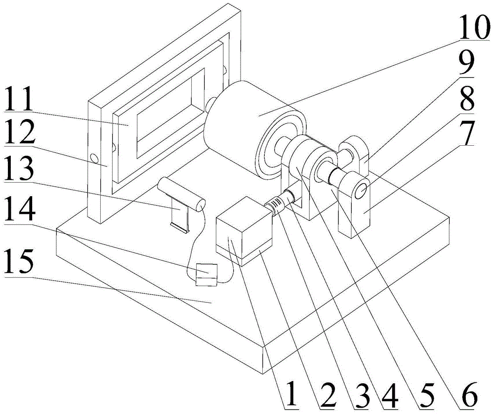
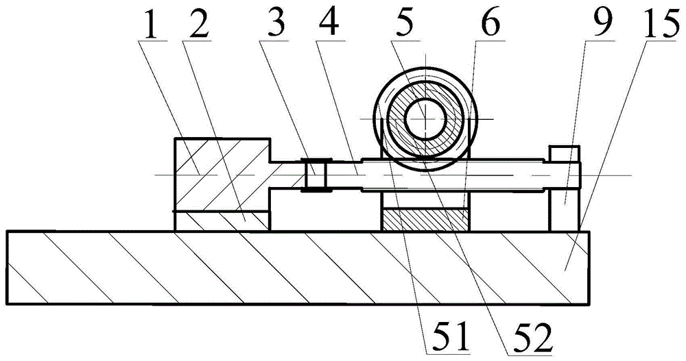
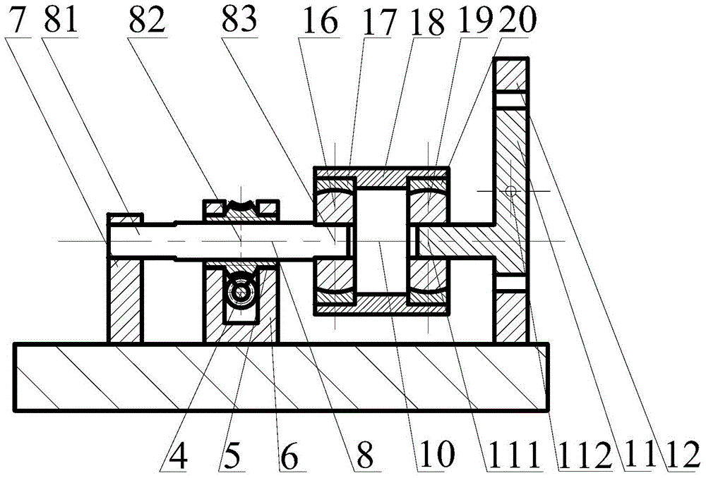
[0019] see figure 1 , figure 1 It is a structural schematic diagram of the device for adjusting the pitch angle of the mirror frame of the present invention. As can be seen from the figure, the composition of the frame pitch angle adjustment device of the present invention includes: the rotating shaft of the stepping motor 1 is connected with one end of the worm 4 through the hinge 3, and the worm 4 and the turbine 51 cooperate to form a worm and worm structure. By adjusting the height of the motor base 2 , eliminating the gap between the turbine and worm structures, ensuring the movement accuracy of the structure, and the other end of the worm is supported on the platform 15 through the worm support arm. Screw mandrel 8 is divided into three sections 81, 82 and 83, and its structural schematic diagram is as Figure 5 As shown, the screw rod 82 passes through the screw hole 52 in the shaft of the turbine to cooperate to form a screw nut pair structure. The picture frame 11 ...


PUM


Abstract

A pitch angle adjusting device of a picture frame comprises a platform, a stepping motor, a hinge, a worm, a worm supporting arm, a worm gear, a worm gear supporting frame, a lead screw, a lead screw supporting arm, a motion assembly, the picture frame, a picture frame supporting seat, an angular instrument and a computer. The problems that due to limiting instability of a spring mechanism, the angle of an optical element drifts, and due to the fact that dead areas exist in the reciprocating motion of a guide rail mechanism, repeated locating precision is reduced are solved. The motion assembly comprises two inner rings, two outer rings and outer ring fixed sleeves. The pitch angle adjusting device has the advantages that rigid connection and structural stability between structural parts are good, the pitch angle precision of the picture frame is adjustable, the device is light and easy to maintain, the pitch angle adjusting device is applied to an optical element of a high-power laser device to adjust the angle, and batch production can be achieved.

Description

technical field [0001] The invention relates to a mirror frame, in particular to a device for adjusting the pitch angle of the mirror frame. Background technique [0002] The angle adjustment device of the mirror frame is a high-precision device that adjusts the posture of the optical element. In the adjustment of the optical path, there are problems such as drifting of the angle of the optical element, low stability, and empty back in the reverse transmission. The display method is to constantly adjust the posture of the frame to the required angle artificially, which is time-consuming, laborious and inefficient. Contents of the invention [0003] The object of the present invention is to provide a rigidly connected mirror frame angle adjustment device. It aims to solve the problems of angular drift of the optical element caused by the instability of the limit of the spring mechanism, and the dead zone of the reciprocating movement of the guide rail mechanism, resulting...

Claims


Application Information

Patent Timeline
IPC IPC(8): F16H37/12H02K7/10
CPCF16H37/12H02K7/10
Inventor 朱健强吴永忠焦翔李养帅尹进
Owner SHANGHAI INST OF OPTICS & FINE MECHANICS CHINESE ACAD OF SCI
Learn More