A high-efficiency method for manufacturing a moving iron unit diaphragm

A high-efficiency, moving iron technology, applied in the direction of electrical components, sensors, etc., can solve the problems of low production efficiency, difficult quality assurance, cumbersome production methods, etc., and achieve high processing efficiency, convenient molding, and high product dimensional accuracy.

Active Publication Date: 2018-04-10
CHANGZHOU AMT
View PDF9 Cites 0 Cited by
  • Summary
  • Abstract
  • Description
  • Claims
  • Application Information

AI Technical Summary

Problems solved by technology

[0007] The purpose of the present invention is to overcome the deficiencies of the existing moving-iron unit diaphragm manufacturing method which are relatively cumbersome, low production efficiency, and difficult to guarantee quality, and provide a high-efficiency method for manufacturing the moving-iron unit diaphragm, adopting the technical solution of the present invention , Multiple products can be formed in a single process, and the production process is simpler and more convenient, which greatly improves the production efficiency of the diaphragm; the diaphragm is formed once, without subsequent bending, the product quality is more stable, and it is easy to realize automated mass production

Method used


Image

  • A high-efficiency method for manufacturing a moving iron unit diaphragm
  • A high-efficiency method for manufacturing a moving iron unit diaphragm
  • A high-efficiency method for manufacturing a moving iron unit diaphragm

Examples


Embodiment 1

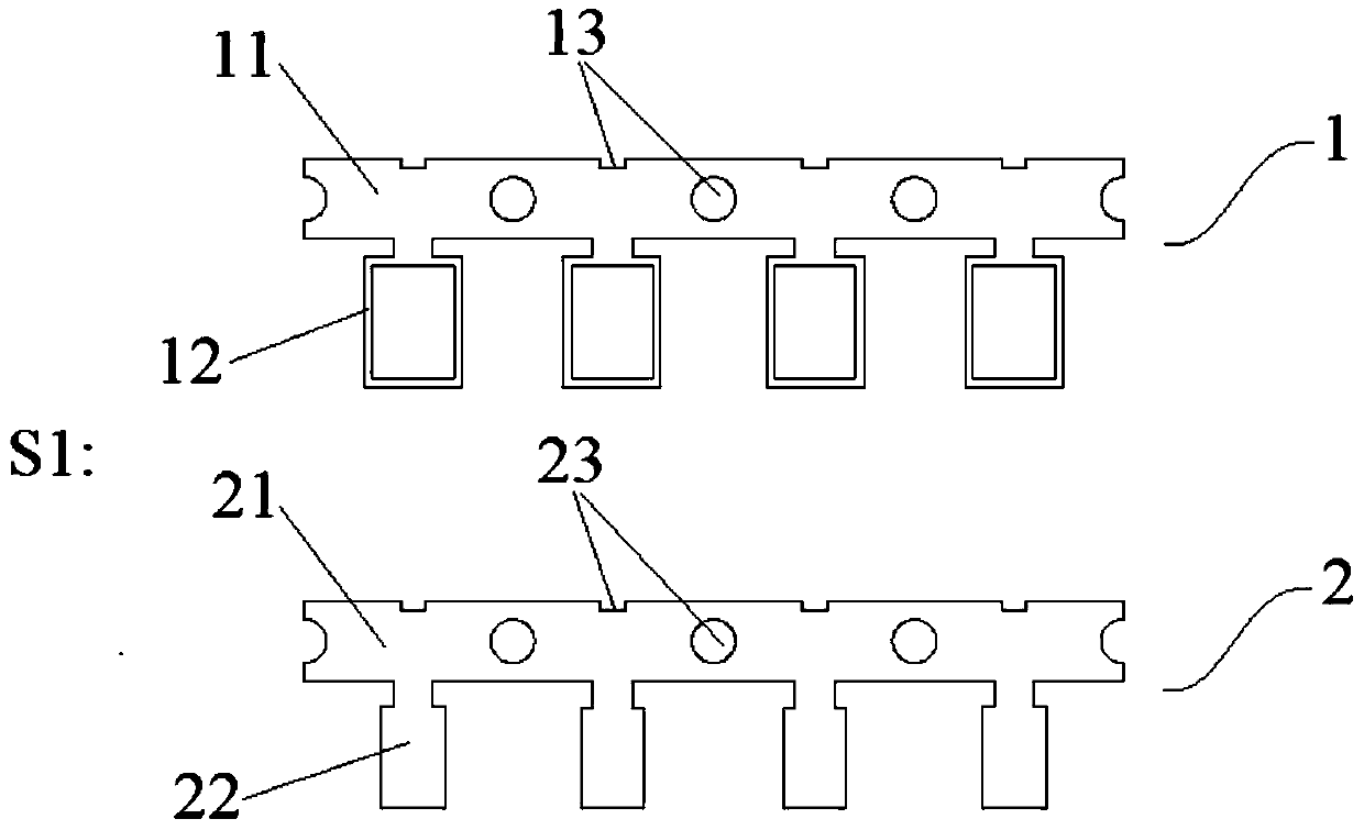
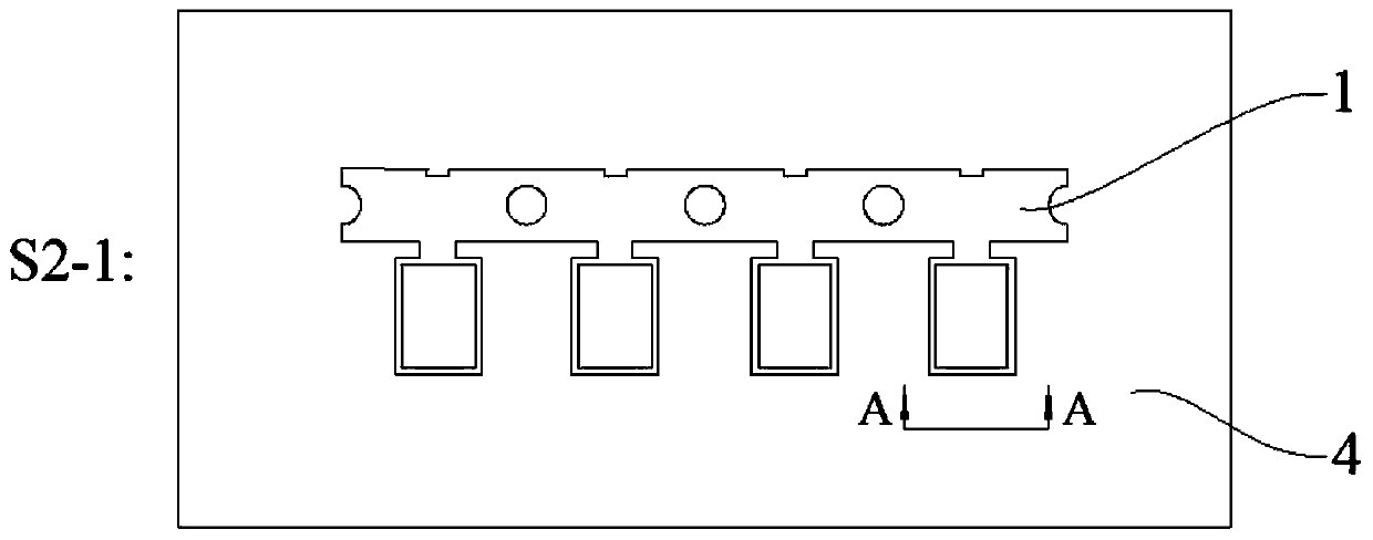
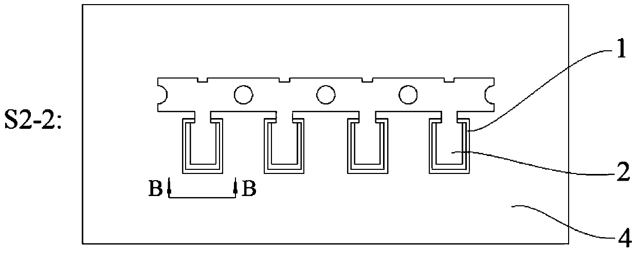
[0047] combine Figure 1 to Figure 5 As shown, a high-efficiency method for manufacturing a moving iron unit diaphragm in this embodiment includes the following process steps:

[0048] S1. Make the diaphragm support sheet group 1 and the diaphragm main sheet group 2, such as figure 1 As shown, the diaphragm support sheet group 1 includes a support strip 11 and two or more diaphragm supports 12 integrally connected to the support strip 11, and both sides of the diaphragm support 12 are formed with folded edges 14 ( see Figure 7 As shown), the bracket strip 11 is also provided with a bracket positioning hole 13, which is used for the positioning of the diaphragm bracket sheet group 1; the diaphragm main body sheet group 2 includes a main body strip 21 and a The diaphragm main body 22 having the same number as the diaphragm support 12 is provided with a main body positioning hole 23 on the main body strip 21 for the positioning of the diaphragm main sheet group 2; specifically...

Embodiment 2

[0059] A high-efficiency method for manufacturing a moving iron unit diaphragm in this embodiment, its process steps are basically the same as in Embodiment 1, the difference is that the diaphragm support 12 in this embodiment is on both sides of the support strip 11, respectively. The spacing is set, and the diaphragm main body 22 is also arranged at equal intervals on both sides of the main material belt 21, that is, the diaphragm support 12 and the diaphragm main body 22 are evenly distributed on both sides of the corresponding material belt according to certain rules, and are not limited to implementation. Single-row design in Example 1; and in this embodiment, four diaphragm supports 12 are arranged at equal intervals on both sides of the support strip 11, and four diaphragm supports are also arranged at equal intervals on both sides of the main body strip 21. The diaphragm main body 22 can complete the production of eight diaphragms 6 in one positioning, and the productio...


PUM


Abstract

The invention discloses a high-efficiency method for manufacturing a vibrating membrane of a moving iron unit, belonging to the technical field of loudspeaker vibrating membranes. The steps of the present invention are: S1, making the diaphragm support sheet group and the diaphragm main body sheet group; S2, placing the prepared diaphragm support sheet group, the diaphragm main body sheet group and the film on the lower mold in no particular order , and use the bracket positioning hole and the main body positioning hole to position; S3, send the lower mold to the hot press, use the soft upper mold and the lower mold to heat press to make the diaphragm bracket and the diaphragm main body It is connected with the film as a whole; S4, take out the integrated diaphragm support sheet group, diaphragm main body sheet group and film, and cut off the excess film, frame material strip and main body strip to obtain a diaphragm with folded edges and a runway . The present invention can form a plurality of diaphragms in a single process, the process steps are simpler, and the production efficiency of the diaphragms is greatly improved; the diaphragms are formed once, without subsequent bending, the product quality is more stable, and it is easy to realize automatic production.

Description

technical field [0001] The invention relates to a method for manufacturing a loudspeaker diaphragm, and more specifically, relates to a method for manufacturing a moving iron unit diaphragm with high efficiency. Background technique [0002] At present, because the performance of the moving iron unit in the middle and high range is better than that of the moving coil unit, the moving iron unit is widely used in many earphones and speakers. The working principle of the moving iron unit is: the moving iron unit uses the basic principle of electromagnetic conversion. When working, the AC current signal passes through the magnetic induction coil, and the coil induces magnetization, which magnetizes the balanced armature (shrapnel) located in the middle of the coil and is magnetized. The balanced armature vibrates up and down in the two permanent magnets according to the principle that the same sex repels each other and the opposite sex attracts each other. The sounding diaphrag...

Claims


Application Information

Patent Timeline
Patent Type & Authority Patents(China)
IPC IPC(8): H04R31/00
Inventor 魏鹏孟献振曾伟
Owner CHANGZHOU AMT
Why Eureka
Try Eureka